ELECTRONIC SHIFT LEVER SYSTEM, Diagnostic DTC:P272C00
| DTC Code | DTC Name |
|---|---|
| P272C00 | Park Pawl Motor Driving Time Too Long |
DESCRIPTION
The hybrid vehicle control ECU receives a P position switch signal from the P position switch (transmission shift main switch) and operates the parking lock motor through current control to engage and release the parking lock.
If the hybrid vehicle control ECU detects a malfunction when operating the shift control actuator assembly, it stores this DTC.
| DTC No. | Detection Item | DTC Detection Condition | Trouble Area | Warning Indicate | Memory |
|---|---|---|---|---|---|
| P272C00 | Park Pawl Motor Driving Time Too Long | A shift control actuator assembly (parking lock motor) internal malfunction (parking lock motor spins freely) is detected for 2 seconds or more. |
|
|
DTC stored |
CONFIRMATION DRIVING PATTERN
Tech Tips
After repairs have been completed, clear the DTCs and then check that the vehicle has returned to normal by performing the following All Readiness check procedure.
-
Turn the power switch on (IG).
-
With the brake pedal depressed, select neutral (N).
-
Push the P position switch (transmission shift main switch).
CAUTION / NOTICE / HINT
Note
After turning the power switch off, waiting time may be required before disconnecting the cable from the negative (-) auxiliary battery terminal. Therefore, make sure to read the disconnecting the cable from the negative (-) auxiliary battery terminal notices before proceeding with work.
PROCEDURE
-
CHECK SHIFT CONTROL ACTUATOR ASSEMBLY
Result Proceed to OK NG
-
Check that the parking brake is applied.
-
Disconnect the C2 shift control actuator assembly connector.
-
Remove the 3 shift control actuator bolts.
Tech Tips
-
Slightly pull the shift control actuator assembly from the hybrid vehicle transaxle assembly.
-
Reconnect the C2 shift control actuator assembly connector.
-
Release the brake pedal and turn the power switch on (ACC).
Note
The shift control actuator assembly may operate if the power switch is turned on (IG) or (READY). Do not turn the power switch on (IG) or (READY) during this inspection to prevent the shift control actuator assembly from operating while in contact with the splines.
-
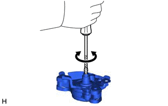
Using a screwdriver with its tip wrapped with protective tape or a piece of cloth, rotate the shaft.
Note
-
During this inspection, make sure to use a screwdriver with its tip wrapped with protective tape or a piece of cloth to prevent the splines of the actuator from being damaged.
-
The shift control actuator assembly cannot be disassembled.
-
Confirm that the shaft of the shift control actuator assembly rotates smoothly.
OK The shaft of the shift control actuator assembly rotates smoothly. -
Measure the voltage according to the value(s) in the table below.
Note
When measuring the voltage, turn the shift control actuator assembly slowly.
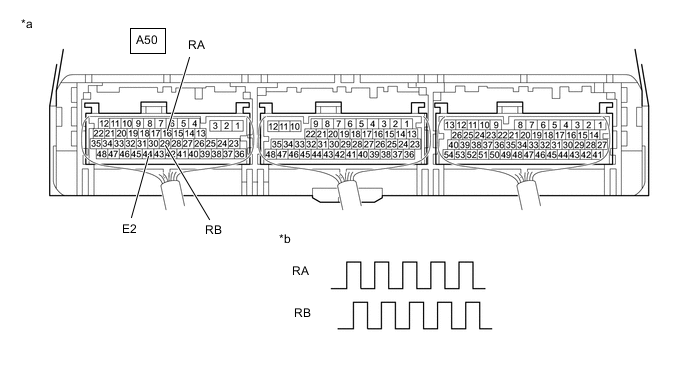
*a Component with harness connected
(Hybrid Vehicle Control ECU)
*b Output Waveform while Splines of Shift Control Actuator Assembly being Rotated (Example) Standard Voltage Tester Connection Condition Specified Condition A50-16 (RA) - A50-44 (E2) Power switch on (ACC), shaft of shift control actuator assembly being rotated 0 to 1.5 V ←→ 4 to 5.5 V A50-29 (RB) - A50-44 (E2) Power switch on (ACC), shaft of shift control actuator assembly being rotated 0 to 1.5 V ←→ 4 to 5.5 V
-
-
Turn the power switch off.
Result Proceed to OK NG
NG 
REPLACE SHIFT CONTROL ACTUATOR ASSEMBLY Click here
OK 
-
-
CHECK HYBRID VEHICLE TRANSAXLE ASSEMBLY
Result Proceed to OK NG
-
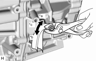
*a Lock *b Unlock *c Rotate approximately 20° Wrap the shaft with a piece of cloth and turn it using pliers.
OK The shaft rotates smoothly in the lock and unlock directions. Note
-
Rotate the shaft using torque between 4.0 and 7.0 N*m (41 and 71 kgf*cm, 36 and 61 in.*lbf).
-
During this inspection, make sure to use a piece of cloth to prevent the shaft splines from being damaged.
-
-
Set the shaft in the lock position after the inspection.
Result Proceed to OK NG
OK
REPLACE HYBRID VEHICLE CONTROL ECU Click here
NG
REPLACE HYBRID VEHICLE TRANSAXLE ASSEMBLY Click here
-