ELECTRONIC SHIFT LEVER SYSTEM, Diagnostic DTC:P1C8F14, P1C9414, P1C9914
| DTC Code | DTC Name |
|---|---|
| P1C8F14 | Park Pawl Motor Phase U Circuit Short to Ground or Open |
| P1C9414 | Park Pawl Motor Phase V Circuit Short to Ground or Open |
| P1C9914 | Park Pawl Motor Phase W Circuit Short to Ground or Open |
DESCRIPTION
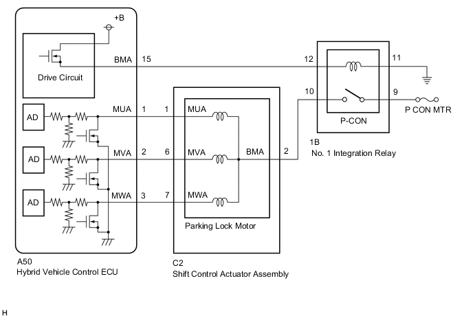
The shift control actuator assembly consists of a parking lock motor and rotation angle sensor. The hybrid vehicle control ECU receives a P position switch signal from the hybrid vehicle control ECU and activates the parking lock motor by controlling current, causing the parking lock mechanism to switch. The hybrid vehicle control ECU stores these DTCs when it detects a malfunction in the parking lock motor system.
| DTC No. | Detection Item | DTC Detection Condition | Trouble Area | Warning Indicate | Memory |
|---|---|---|---|---|---|
| P1C8F14 | Park Pawl Motor Phase U Circuit Short to Ground or Open | When the power switch is on (IG) and the auxiliary battery voltage is 10 V or more, even though the No. 1 integration relay (P-CON relay) operation permission signal is ON, the parking lock motor U phase terminal voltage (AD value recognized by the ECU) is less than 0.4 V for 1 second or more continuously. (1 trip detection logic) |
|
|
DTC stored |
| P1C9414 | Park Pawl Motor Phase V Circuit Short to Ground or Open | When the power switch is on (IG) and the auxiliary battery voltage is 10 V or more, even though the No. 1 integration relay (P-CON relay) operation permission signal is ON, the parking lock motor V phase terminal voltage (AD value recognized by the ECU) is less than 0.4 V for 1 second or more continuously. (1 trip detection logic) |
|
|
DTC stored |
| P1C9914 | Park Pawl Motor Phase W Circuit Short to Ground or Open | When the power switch is on (IG) and the auxiliary battery voltage is 10 V or more, even though the No. 1 integration relay (P-CON relay) operation permission signal is ON, the parking lock motor W phase terminal voltage (AD value recognized by the ECU) is less than 0.4 V for 1 second or more continuously. (1 trip detection logic) |
|
|
DTC stored |
CONFIRMATION DRIVING PATTERN
Tech Tips
After repairs have been completed, clear the DTCs and then check that the vehicle has returned to normal by performing the following All Readiness check procedure.
-
Turn the power switch on (IG).
-
With the brake pedal depressed, select neutral (N).
-
Push the P position switch (transmission shift main switch).
WIRING DIAGRAM
CAUTION / NOTICE / HINT
Note
-
Do not remove/install the auxiliary battery or disconnect the cable from the negative (-) auxiliary battery terminal before instructed.
-
Do not disconnect the connectors before instructed.
-
After turning the power switch off, waiting time may be required before disconnecting the cable from the negative (-) auxiliary battery terminal. Therefore, make sure to read the disconnecting the cable from the negative (-) auxiliary battery terminal notices before proceeding with work.
-
If DTC P1C8F14, P1C9414 or P1C9914 is stored, the P-CON relay will be turned off as a fail-safe.
-
Inspect the fuses for circuits related to this system before performing the following procedure.
PROCEDURE
-
CHECK DTC OUTPUT (HYBRID CONTROL)
-
Connect the GTS to the DLC3.
-
Turn the power switch on (IG).
-
Enter the following menus: Powertrain / Hybrid Control / Trouble Codes.
Powertrain > Hybrid Control > Trouble Codes -
Check if DTCs are output.
Result Result Proceed to P1C8F14, P1C9414 and P1C9914 are output simultaneously A Only P1C8F14, P1C9414 or P1C9914 is output B Tech Tips
-
If DTCs P1C8F14, P1C9414 and P1C9914 are stored at the same time, there may be a malfunction in the parking lock motor (BMA signal) power source circuit.
-
If only DTC P1C8F14, P1C9414 or P1C9914 is stored, there may be a malfunction in the parking lock motor (MUA, MVA or MWA) circuit
-
-
Turn the power switch off.
B 
GO TO STEP 7 Click here
A 
-
-
CHECK HARNESS AND CONNECTOR (P-CON RELAY POWER SOURCE CIRCUIT)
-
Disconnect the 1B No. 1 integration relay connector.
-
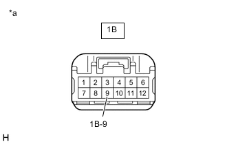
*a Front view of wire harness connector
(to No. 1 Integration Relay)
Measure the voltage according to the value(s) in the table below.
Standard Voltage Tester Connection Condition Specified Condition 1B-9 - Body ground Always 9 to 14 V -
Reconnect the 1B No. 1 integration relay connector.
Result Proceed to OK NG
NG
CHECK HARNESS AND CONNECTOR (AUXILIARY BATTERY - P-CON RELAY) Click here
OK
-
-
CHECK HARNESS AND CONNECTOR (P-CON RELAY - BODY GROUND)
-
Disconnect the 1B No. 1 integration relay connector.
-
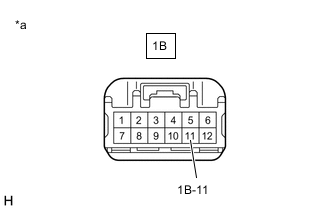
*a Front view of wire harness connector
(to No. 1 Integration Relay)
Measure the resistance according to the value(s) in the table below.
Standard Resistance (Check for Open) Tester Connection Condition Specified Condition 1B-11 - Body ground Power switch off Below 1 Ω -
Reconnect the 1B No. 1 integration relay connector.
Result Proceed to OK NG
NG 
REPAIR OR REPLACE HARNESS OR CONNECTOR
OK
-
-
INSPECT NO. 1 INTEGRATION RELAY (P-CON RELAY)
Result Proceed to OK NG
NG
REPLACE NO. 1 INTEGRATION RELAY (P-CON RELAY) Click here
OK
-
CHECK HARNESS AND CONNECTOR (SHIFT CONTROL ACTUATOR ASSEMBLY - P-CON RELAY)
-
Disconnect the C2 shift control actuator assembly connector.
-
Disconnect the 1B No. 1 integration relay connector.
Tech Tips
-
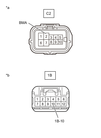
*a Front view of wire harness connector
(to Shift Control Actuator Assembly)
*b Front view of wire harness connector
(to No. 1 Integration Relay)
Measure the resistance according to the value(s) in the table below.
Standard Resistance (Check for Open) Tester Connection Condition Specified Condition C2-2(BMA) - 1B-10 Power switch off Below 1 Ω Standard Resistance (Check for Short) Tester Connection Condition Specified Condition C2-2(BMA) or 1B-10 - Body ground and other terminals Power switch off 10 kΩ or higher -
Reconnect the 1B No. 1 integration relay connector.
-
Reconnect the C2 shift control actuator assembly connector.
Result Proceed to OK NG
NG
REPAIR OR REPLACE HARNESS OR CONNECTOR
OK
-
-
CHECK HARNESS AND CONNECTOR (HYBRID VEHICLE CONTROL ECU - P-CON RELAY)
-
Disconnect the A50 hybrid vehicle control ECU connector.
-
Disconnect the 1B No. 1 integration relay connector.
-
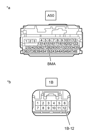
*a Front view of wire harness connector
(to Hybrid Vehicle Control ECU)
*b Front view of wire harness connector
(to No. 1 Integration Relay)
Measure the resistance according to the value(s) in the table below.
Standard Resistance (Check for Open) Tester Connection Condition Specified Condition A50-15 (BMA) - 1B-12 Power switch off Below 1 Ω Standard Resistance (Check for Open) Tester Connection Condition Specified Condition A50-15 (BMA) or 1B-12 - Body ground and other terminals Power switch off 10 kΩ or higher -
Reconnect the 1B No. 1 integration relay connector.
-
Reconnect the A50 hybrid vehicle control ECU connector.
Result Proceed to OK NG
NG
REPAIR OR REPLACE HARNESS OR CONNECTOR
OK
-
-
CHECK HARNESS AND CONNECTOR (HYBRID VEHICLE CONTROL ECU - SHIFT CONTROL ACTUATOR ASSEMBLY)
-
Disconnect the A50 hybrid vehicle control ECU connector.
-
Disconnect the C2 shift control actuator assembly connector.
-
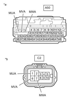
*a Front view of wire harness connector
(to Hybrid Vehicle Control ECU)
*b Front view of wire harness connector
(to Shift Control Actuator Assembly)
Measure the resistance according to the value(s) in the table below.
Standard Resistance (Check for Open) Tester Connection Condition Specified Condition A50-1 (MUA) - C2-1 (MUA) Power switch off Below 1 Ω A50-2 (MVA) - C2-6 (MVA) Power switch off Below 1 Ω A50-3 (MWA) - C2-7 (MWA) Power switch off Below 1 Ω Standard Resistance (Check for Short) Tester Connection Condition Specified Condition A50-1 (MUA) or C2-1 (MUA) - Body ground and other terminals Power switch off 10 kΩ or higher A50-2 (MVA) or C2-6 (MVA) - Body ground and other terminals Power switch off 10 kΩ or higher A50-3 (MWA) or C2-7 (MWA) - Body ground and other terminals Power switch off 10 kΩ or higher -
Reconnect the C2 shift control actuator assembly connector.
-
Reconnect the A50 hybrid vehicle control ECU connector.
Result Proceed to OK NG
NG
REPAIR OR REPLACE HARNESS OR CONNECTOR
OK
-
-
CHECK SHIFT CONTROL ACTUATOR ASSEMBLY (PARKING LOCK MOTOR)
-
Disconnect the C2 shift control actuator assembly connector.
-
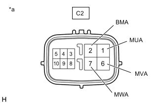
*a Component without harness connected
(Shift Control Actuator Assembly)
Measure the resistance according to the value(s) in the table below.
Standard Resistance (Check for Open) Tester Connection Condition Specified Condition C2-1(MUA) - C2-2(BMA) Power switch off 0.5 to 2 Ω C2-6(MVA) - C2-2(BMA) Power switch off 0.5 to 2 Ω C2-7(MWA) - C2-2(BMA) Power switch off 0.5 to 2 Ω C2-1(MUA) - C2-6(MVA) Power switch off 1 to 4 Ω C2-6(MVA) - C2-7(MWA) Power switch off 1 to 4 Ω C2-7(MWA) - C2-1(MUA) Power switch off 1 to 4 Ω Standard Resistance (Check for Short) Tester Connection Condition Specified Condition C2-1 (MUA) - Body ground Power switch off 10 kΩ or higher C2-6 (MVA) - Body ground Power switch off 10 kΩ or higher C2-7 (MWA) - Body ground Power switch off 10 kΩ or higher -
Reconnect the C2 shift control actuator assembly connector.
Result Proceed to OK NG
OK
REPLACE HYBRID VEHICLE CONTROL ECU Click here
NG
REPLACE SHIFT CONTROL ACTUATOR ASSEMBLY Click here
-
-
CHECK HARNESS AND CONNECTOR (AUXILIARY BATTERY - P-CON RELAY)
-
Disconnect the cable from the negative (-) auxiliary battery terminal.
-
Disconnect the cable from the positive (+) auxiliary battery terminal.
-
Disconnect the 1B No. 1 integration relay connector.
-
*a Front view of wire harness connector
(to No. 1 Integration Relay)
Measure the resistance according to the value(s) in the table below.
Standard Resistance (Check for Open) Tester Connection Condition Specified Condition Auxiliary battery positive (+) cable - 1B-9 Power switch off Below 1 Ω Standard Resistance (Check for Short) Tester Connection Condition Specified Condition Auxiliary battery positive (+) cable or 1B-9 - Body ground and other terminals Power switch off 10 kΩ or higher -
Reconnect the 1B No. 1 integration relay connector.
-
Connect the cable to the positive (+) auxiliary battery terminal.
-
Connect the cable to the negative (-) auxiliary battery terminal.
Result Proceed to OK NG
NG
REPAIR OR REPLACE HARNESS OR CONNECTOR
OK
-
-
CHARGE AUXILIARY BATTERY
-
Charge the auxiliary battery.
Result Proceed to NEXT
NEXT
-
-
CLEAR DTC
-
Connect the Techstream to the DLC3.
-
Turn the power switch on (IG).
-
Enter the following menus: Powertrain / Hybrid Control / Trouble Codes.
-
Clear the DTCs.
Powertrain > Hybrid Control > Clear DTCs -
Disconnect the Techstream from the DLC3.
-
Turn the power switch off.
-
Leave the vehicle as is for 60 seconds or more.
Note
-
Do not connect the Techstream.
-
Do not depress brake pedal.
-
Do not open/close any of the doors.
Result Proceed to NEXT -
NEXT
-
-
CHECK DTC OUTPUT (SIMULATION TEST)
-
Connect the GTS to the DLC3.
-
With the brake pedal released, turn the power switch on (IG) and wait for 10 seconds or more.
Tech Tips
Do not turn the power switch on (READY).
-
Depress the brake pedal and select neutral (N).
-
Push the P position switch (transmission shift main switch).
-
Enter the following menus: Powertrain / Hybrid Control / Trouble Codes.
-
Check if DTCs are output.
Powertrain > Hybrid Control > Trouble CodesResult Result Proceed to P1C8F14, P1C9414 or P1C9914 is output A P1C8F14, P1C9414 and P1C9914 are not output B -
Turn the power switch off.
A
REPLACE AUXILIARY BATTERY Click here
B
END
-