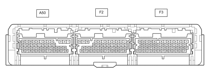
ELECTRONIC SHIFT LEVER SYSTEM TERMINALS OF ECU
-
CHECK HYBRID VEHICLE CONTROL ECU
Tech Tips
Measure the values on the wire harness side with the connector connected.
Terminal No. (Symbol) Wiring Color Terminal Description Condition Specified Condition A50-1 (MUA) - F2-12 (E01) B - W-B Parking lock motor Engine stopped (hybrid system stopped), power switch on (IG) 9 to 14 V A50-2 (MVA) - F2-12 (E01) R - W-B Parking lock motor Engine stopped (hybrid system stopped), power switch on (IG) 9 to 14 V A50-3 (MWA) - F2-12 (E01) W - W-B Parking lock motor Engine stopped (hybrid system stopped), power switch on (IG) 9 to 14 V A50-5 (MREL) - F3-3 (E1) BE - W-B Main relay Power switch on (IG) 9 to 14 V A50-11 (+B1) - F3-3 (E1) L - W-B Power source Engine stopped (hybrid system stopped), power switch on (IG) 9 to 14 V A50-15 (BMA) - F3-3 (E1) R - W-B No. 1 integration relay (P-CON relay) Engine stopped (hybrid system stopped), power switch on (IG) 9 to 14 V A50-16 (RA) - A50-44 (E2) LG - P Rotation angle sensor signal Power switch off → Power switch on (IG) 0 to 1.5 V ←→ 4 to 5.5 V Power switch on (IG),
changing from park (P) to neutral (N), or neutral (N) to park (P)
Pulse generation (see waveform 1) A50-41 (VC) - A50-44 (E2) G - P Power source (Rotation angle sensor) Engine stopped (hybrid system stopped), power switch on (IG) 4.5 to 5.5 V A50-29 (RB) - A50-44 (E2) GR - P Rotation angle sensor signal Power switch off → Power switch on (IG) 0 to 1.5 V ←→ 4 to 5.5 V Power switch on (IG),
changing from park (P) to neutral (N), or neutral (N) to park (P)
Pulse generation
(see waveform 1)
A50-44 (E2) - Body ground P - Body ground Rotation angle sensor ground Always Below 1 Ω F2-7 (CA3P) - F3-3 (E1) G - W-B CAN communication signal Power switch on (IG) Pulse generation (see waveform 2) F2-10 (E03) - Body ground W-B - Body ground Ground Always Below 1 Ω F2-11 (E02) - Body ground W-B - Body ground Ground Always Below 1 Ω F2-12 (E01) - Body ground W-B - Body ground Ground Always Below 1 Ω F2-20 (CA3N) - F3-3 (E1) W - W-B CAN communication signal Power switch on (IG) Pulse generation (see waveform 2) F2-34 (E12) - Body ground W-B - Body ground Ground Always Below 1 Ω F3-1 (+B2) - F3-3 (E1) L - W-B Power source Power switch on (IG) 9 to 14 V F3-3 (E1) - Body ground W-B - Body ground Ground Always Below 1 Ω F3-6 (PPOS) - F3-3 (E1) V - W-B Transmission control communication signal Engine stopped (hybrid system stopped), power switch on (IG) Pulse generation (see waveform 3) F3-13 (P1) - F3-3 (E1) LG - W-B P position switch signal Power switch on (IG), P position switch (transmission shift main switch) not pushed 7 to 12 V Power switch on (IG), P position switch (transmission shift main switch) pushed 3 to 5 V F3-27 (BATT) - F3-3 (E1) GR - W-B Power source (RAM) Always 9 to 14 V F3-31 (LIN) L*1, BE*2 LIN communication - - F3-39 (IND) - F3-3 (E1) P - W-B P position switch indicator light Park (P) not selected → Park (P) selected (P position switch (transmission shift main switch) pushed to select park (P)) 9 to 14 V → 0 to 1.5 V
-
*1: for LHD
-
*2: for RHD
-
-
OSCILLOSCOPE WAVEFORMS
Tech Tips
Oscilloscope waveform samples are provided here for reference only. Noise and fluctuating waveforms have been omitted.
-
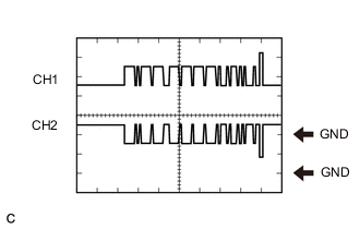
Waveform 1 (Rotation angle sensor signal)
Item Contents Terminal CH1: A50-16 (RA) - A50-44 (E2)
CH2: A50-29 (RB) - A50-44 (E2)
Equipment setting 2 V/DIV., 200 msec./DIV. Condition Power switch on (IG),
changing from park (P) to neutral (N), or neutral (N) to park (P)
Tech Tips
When changing from park (P) to neutral (N), or neutral (N) to park (P) with the power switch on (IG), a waveform will be generated for up to 1.5 seconds.
-
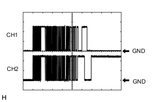
Waveform 2 (CAN communication signal)
Item Contents Terminal CH1: F2-7 (CA3P) - F3-3 (E1)
CH2: F2-20 (CA3N) - F3-3 (E1)
Equipment setting 1 V/DIV., 50 μs/DIV. Condition Power switch on (IG) -
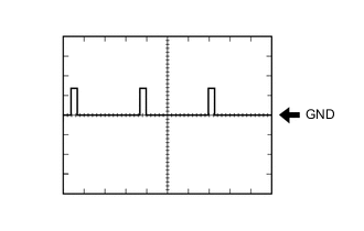
Waveform 3 (Transmission control communication signal)
Item Contents Terminal F3-6 (PPOS) - F3-3 (E1) Equipment setting 10 V/DIV., 10 ms/DIV. Condition Engine stopped (hybrid system stopped), power switch on (IG)
-