SIMPLE INTELLIGENT PARKING ASSIST SYSTEM Main Switch Circuit
DESCRIPTION
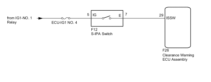
When the S-IPA switch is turned on, a signal is sent to the clearance warning ECU assembly. The simple intelligent parking assist system operates according to this signal.
WIRING DIAGRAM
PROCEDURE
-
READ VALUE USING GTS (IPA SWITCH)
-
Connect the GTS to the DLC3.
-
Turn the power switch to (IG).
-
Turn the GTS on.
-
Enter the following menus: Body Electrical / IPA/ICS/Clearance Sonar / Data List / IPA Switch.
-
Read the value when the S-IPA switch is pressed.
Body Electrical > IPA/ICS/Clearance Sonar > Data ListTester Display Measurement Item Normal Condition IPA Switch S-IPA signal ON: S-IPA switch on
OFF: S-IPA switch off
Result Proceed to OK NG
OK 
PROCEED TO NEXT SUSPECTED AREA SHOWN IN PROBLEM SYMPTOMS TABLE Click here
NG 
-
-
INSPECT S-IPA SWITCH
-
Remove the S-IPA switch.
-
Inspect the S-IPA switch.
OK S-IPA switch is normal. Result Proceed to OK NG
NG
REPLACE S-IPA SWITCH Click here
OK
-
-
CHECK HARNESS AND CONNECTOR (S-IPA SWITCH - AUXILIARY BATTERY)
-
Disconnect the F12 S-IPA switch connector.
-
Measure the voltage according to the value(s) in the table below.
Standard Voltage Tester Connection Condition Specified Condition F12-5 (IG) - F26-29 (ISSW) Power switch on (IG) 11 to 14 V Power switch off Below 1 V Result Proceed to OK NG
NG
REPAIR OR REPLACE HARNESS OR CONNECTOR
OK
-
-
CHECK HARNESS AND CONNECTOR (S-IPA SWITCH - CLEARANCE WARNING ECU ASSEMBLY)
-
Disconnect the F12 S-IPA switch connector.
-
Disconnect the F26 clearance warning ECU assembly connector.
-
Measure the resistance according to the value(s) in the table below.
Standard Resistance Tester Connection Condition Specified Condition F12-7 (E) - F26-29 (ISSW) Always Below 1 Ω F12-7 (E) or F26-29 (ISSW) - Body ground Always 10 kΩ or higher Result Proceed to OK NG
OK
PROCEED TO NEXT SUSPECTED AREA SHOWN IN PROBLEM SYMPTOMS TABLE Click here
NG
REPAIR OR REPLACE HARNESS OR CONNECTOR
-