PARKING ASSIST MONITOR SYSTEM Black Screen
DESCRIPTION
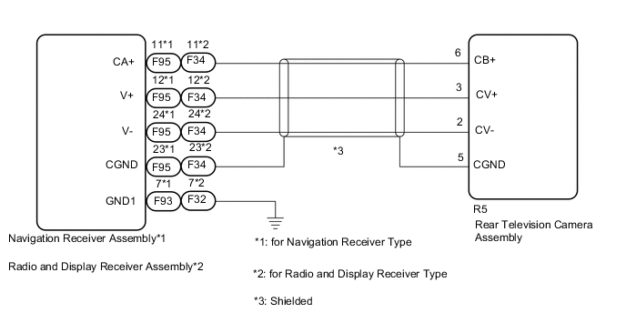
The video signal from the rear television camera assembly is transmitted to the navigation receiver assembly*1 or radio and display receiver assembly*2.
-
*1: for Navigation Receiver Type
-
*2: for Radio and Display Receiver Type
WIRING DIAGRAM
CAUTION / NOTICE / HINT
Note
-
If the cable was disconnected from and reconnected to the negative (-) auxiliary battery terminal, the estimated course lines may not be displayed on the image of the area behind the vehicle. In this case, perform "Correct the Steering Angle Neutral Point".
-
Depending on the parts that are replaced or operations that are performed during vehicle inspection or maintenance, calibration of other systems as well as the parking assist monitor system may be needed.
PROCEDURE
-
CONFIRM MODEL
-
Choose the model to be inspected.
Result Result Proceed to for Navigation Receiver Type A for Radio and Display Receiver Type B
B 
CHECK HARNESS AND CONNECTOR (RADIO AND DISPLAY RECEIVER ASSEMBLY - REAR TELEVISION CAMERA ASSEMBLY) Click here
A 
-
-
CHECK HARNESS AND CONNECTOR (NAVIGATION RECEIVER ASSEMBLY - REAR TELEVISION CAMERA ASSEMBLY)
Result Proceed to OK NG
-
Disconnect the F95 navigation receiver assembly connector.
-
Disconnect the R5 rear television camera assembly connector.
-
Measure the resistance according to the value(s) in the table below.
Standard Resistance Tester Connection Condition Specified Condition F95-11 (CA+) - R5-6 (CB+) Always Below 1 Ω F95-12 (V+) - R5-3 (CV+) Always Below 1 Ω F95-24 (V-) - R5-2 (CV-) Always Below 1 Ω F95-23 (CGND) - R5-5 (CGND) Always Below 1 Ω F95-11 (CA+) or R5-6 (CB+) - Body ground Always 10 kΩ or higher F95-12 (V+) or R5-3 (CV+) - Body ground Always 10 kΩ or higher F95-24 (V-) or R5-2 (CV-) - Body ground Always 10 kΩ or higher F95-23 (CGND) or R5-5 (CGND) - Body ground Always 10 kΩ or higher Result Proceed to OK NG
NG 
REPAIR OR REPLACE HARNESS OR CONNECTOR
OK
-
-
INSPECT NAVIGATION RECEIVER ASSEMBLY (CA+, CGND)
Result Proceed to OK NG
-
Reconnect the F95 navigation receiver assembly connector.
-
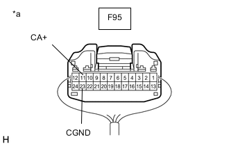
*a Component with harness connected
(Navigation Receiver Assembly)
Measure the resistance according to the value(s) in the table below.
Standard Resistance Tester Connection Condition Specified Condition F95-23 (CGND) - Body ground Always Below 1 Ω -
Measure the voltage according to the value(s) in the table below.
Standard Voltage Tester Connection Condition Specified Condition F95-11 (CA+) - F95-23 (CGND) Power switch on (ACC) 5.5 to 7.05 V Result Proceed to OK NG
NG
REPLACE NAVIGATION RECEIVER ASSEMBLY Click here
OK
-
-
INSPECT NAVIGATION RECEIVER ASSEMBLY (V+, GND1)
Result Proceed to OK NG
-
Reconnect the R5 rear television camera assembly connector.
-

*a Component with harness connected
(Navigation Receiver Assembly)
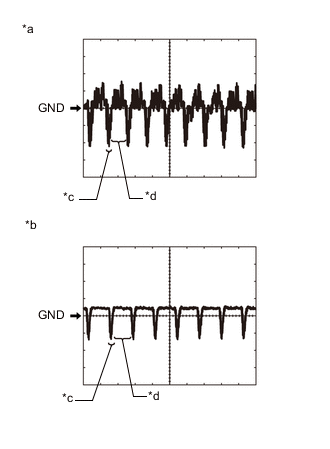
*a Waveform 1 (camera lens is not covered, displaying an image) *b Waveform 2 (camera lens is covered, blacking out the screen) *c Synchronization Signal *d Video Waveform Using an oscilloscope, check the waveform of the rear television camera assembly.
Tech Tips
A waterproof connector is used for the rear television camera assembly. Therefore, inspect the waveform at the navigation receiver assembly with the connector connected.
OK Waveform is similar to that shown in the illustration. Item Content Measurement terminal F95-12 (V+) - F93-7 (GND1) Measurement setting 200 mV/DIV., 50 μs./DIV. Condition Power switch on (IG), reverse (R) selected Tech Tips
-
The video waveform changes according to the image sent by the rear television camera assembly.
-
The video waveform is constantly output when the power switch is on (ACC).
Result Proceed to OK NG -
NG
REPLACE REAR TELEVISION CAMERA ASSEMBLY Click here
OK
-
-
REPLACE NAVIGATION RECEIVER ASSEMBLY
-
Replace the navigation receiver assembly with a new or known good one.
-
Check that the parking assist monitor system operates normally.
OK Parking assist monitor system operates normally. Result Proceed to OK NG
OK
END
NG
REPLACE REAR TELEVISION CAMERA ASSEMBLY Click here
-
-
CHECK HARNESS AND CONNECTOR (RADIO AND DISPLAY RECEIVER ASSEMBLY - REAR TELEVISION CAMERA ASSEMBLY)
Result Proceed to OK NG
-
Disconnect the F34 radio and display receiver assembly connector.
-
Disconnect the R5 rear television camera assembly connector.
-
Measure the resistance according to the value(s) in the table below.
Standard Resistance Tester Connection Condition Specified Condition F34-11 (CA+) - R5-6 (CB+) Always Below 1 Ω F34-12 (V+) - R5-3 (CV+) Always Below 1 Ω F34-24 (V-) - R5-2 (CV-) Always Below 1 Ω F34-23 (CGND) - R5-5 (CGND) Always Below 1 Ω F34-11 (CA+) or R5-6 (CB+) - Body ground Always 10 kΩ or higher F34-12 (V+) or R5-3 (CV+) - Body ground Always 10 kΩ or higher F34-24 (V-) or R5-2 (CV-) - Body ground Always 10 kΩ or higher F34-23 (CGND) or R5-5 (CGND) - Body ground Always 10 kΩ or higher Result Proceed to OK NG
NG
REPAIR OR REPLACE HARNESS OR CONNECTOR
OK
-
-
INSPECT RADIO AND DISPLAY RECEIVER ASSEMBLY (CA+, CGND)
Result Proceed to OK NG
-
Reconnect the F34 radio and display receiver assembly connector.
-
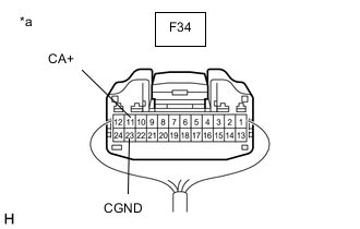
*a Component with harness connected
(Radio and Display Receiver Assembly)
Measure the resistance according to the value(s) in the table below.
Standard Resistance Tester Connection Condition Specified Condition F34-23 (CGND) - Body ground Always Below 1 Ω -
Measure the voltage according to the value(s) in the table below.
Standard Voltage Tester Connection Condition Specified Condition F34-11 (CA+) - F34-23 (CGND) Power switch on (ACC) 5.5 to 7.05 V Result Proceed to OK NG
NG
REPLACE RADIO AND DISPLAY RECEIVER ASSEMBLY Click here
OK
-
-
INSPECT RADIO AND DISPLAY RECEIVER ASSEMBLY (V+, GND1)
Result Proceed to OK NG
-
Reconnect the R5 rear television camera assembly connector.
-
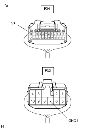
*a Component with harness connected
(Radio and Display Receiver Assembly)
*a Waveform 1 (camera lens is not covered, displaying an image) *b Waveform 2 (camera lens is covered, blacking out the screen) *c Synchronization Signal *d Video Waveform Using an oscilloscope, check the waveform of the rear television camera assembly.
Tech Tips
A waterproof connector is used for the rear television camera assembly. Therefore, inspect the waveform at the radio and display receiver assembly with the connector connected.
OK Waveform is similar to that shown in the illustration. Item Content Measurement terminal F34-12 (V+) - F32-7 (GND1) Measurement setting 200 mV/DIV., 50 μs./DIV. Condition Power switch on (IG), reverse (R) selected Tech Tips
-
The video waveform changes according to the image sent by the rear television camera assembly.
-
The video waveform is constantly output when the power switch is on (ACC).
Result Proceed to OK NG -
NG
REPLACE REAR TELEVISION CAMERA ASSEMBLY Click here
OK
-
-
REPLACE RADIO AND DISPLAY RECEIVER ASSEMBLY
-
Replace the radio and display receiver assembly with a new or known good one.
-
Check that the parking assist monitor system operates normally.
OK Parking assist monitor system operates normally. Result Proceed to OK NG
OK
END
NG
REPLACE REAR TELEVISION CAMERA ASSEMBLY Click here
-