TOYOTA PARKING ASSIST-SENSOR SYSTEM, Diagnostic DTC:C1AEC
| DTC Code | DTC Name |
|---|---|
| C1AEC | Front Sensor Communication Malfunction |
DESCRIPTION
This DTC is stored when there is an open or short circuit in the communication line between the front sensors and the ECU, or when there is a malfunction in a front sensor.
| DTC No. | Detection Item | DTC Detection Condition | Trouble Area |
|---|---|---|---|
| C1AEC | Front Sensor Communication Malfunction | An open or short circuit in the communication line between the front sensors and ECU or a malfunction in a front sensor during initialization mode after the power switch is turned on (IG). |
|
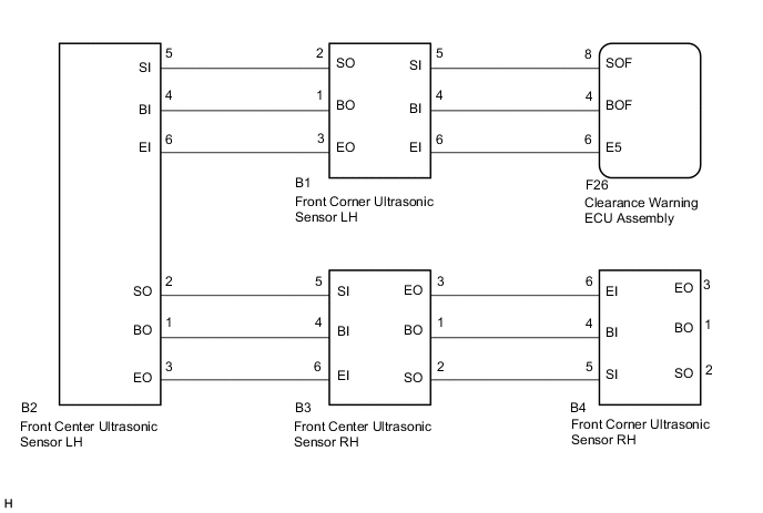
WIRING DIAGRAM
PROCEDURE
-
INTELLIGENT CLEARANCE SONAR SYSTEM REGISTRATION
-
Perform intelligent clearance sonar system registration.
Tech Tips
Result Proceed to NEXT
NEXT 
-
-
CHECK DTC
-
Using the GTS, check for DTCs according to the prompts on the screen.
Body Electrical > IPA/ICS/Clearance Sonar > Trouble CodesResult Proceed to NEXT
NEXT
-
-
CLEAR DTC
-
Clear the DTCs.
Body Electrical > IPA/ICS/Clearance Sonar > Clear DTCsResult Proceed to NEXT
NEXT
-
-
CHECK DTC OUTPUT (C1AEC)
-
Recheck for DTCs and check if the same DTC is output again.
Body Electrical > IPA/ICS/Clearance Sonar > Trouble CodesResult Result Proceed to C1AEC is output A C1AEC is not output B
B 
USE SIMULATION METHOD TO CHECK Click here
A
-
-
CHECK HARNESS AND CONNECTOR (CLEARANCE WARNING ECU ASSEMBLY - FRONT CORNER ULTRASONIC SENSOR LH)
-
Disconnect the F26 clearance warning ECU assembly connector.
-
Disconnect the B1 front corner ultrasonic sensor LH connector.
-
Measure the resistance according to the value(s) in the table below.
Standard Resistance Tester Connection Condition Specified Condition F26-4 (BOF) - B1-4 (BI) Always Below 1 Ω F26-8 (SOF) - B1-5 (SI) Always Below 1 Ω F26-6 (E5) - B1-6 (EI) Always Below 1 Ω F26-4 (BOF) or B1-4 (BI) - Body ground Always 10 kΩ or higher F26-8 (SOF) or B1-5 (SI) - Body ground Always 10 kΩ or higher F26-6 (E5) or B1-6 (EI) - Body ground Always 10 kΩ or higher Result Proceed to OK NG
NG
REPAIR OR REPLACE HARNESS OR CONNECTOR
OK
-
-
CHECK HARNESS AND CONNECTOR (FRONT CORNER ULTRASONIC SENSOR LH - FRONT CENTER ULTRASONIC SENSOR LH)
-
Disconnect the B2 front center ultrasonic sensor LH connector.
-
Measure the resistance according to the value(s) in the table below.
Standard Resistance Tester Connection Condition Specified Condition B1-1 (BO) - B2-4 (BI) Always Below 1 Ω B1-2 (SO) - B2-5 (SI) Always Below 1 Ω B1-3 (EO) - B2-6 (EI) Always Below 1 Ω B1-1 (BO) or B2-4 (BI) - Body ground Always 10 kΩ or higher B1-2 (SO) or B2-5 (SI) - Body ground Always 10 kΩ or higher B1-3 (EO) or B2-6 (EI) - Body ground Always 10 kΩ or higher Result Proceed to OK NG
NG
REPAIR OR REPLACE HARNESS OR CONNECTOR
OK
-
-
CHECK HARNESS AND CONNECTOR (FRONT CENTER ULTRASONIC SENSOR LH - FRONT CENTER ULTRASONIC SENSOR RH)
-
Disconnect the B3 front center ultrasonic sensor RH connector.
-
Measure the resistance according to the value(s) in the table below.
Standard Resistance Tester Connection Condition Specified Condition B2-1 (BO) - B3-4 (BI) Always Below 1 Ω B2-2 (SO) - B3-5 (SI) Always Below 1 Ω B2-3 (EO) - B3-6 (EI) Always Below 1 Ω B2-1 (BO) or B3-4 (BI) - Body ground Always 10 kΩ or higher B2-2 (SO) or B3-5 (SI) - Body ground Always 10 kΩ or higher B2-3 (EO) or B3-6 (EI) - Body ground Always 10 kΩ or higher Result Proceed to OK NG
NG
REPAIR OR REPLACE HARNESS OR CONNECTOR
OK
-
-
CHECK HARNESS AND CONNECTOR (FRONT CENTER ULTRASONIC SENSOR RH - FRONT CORNER ULTRASONIC SENSOR RH)
-
Disconnect the B4 front corner ultrasonic sensor RH connector.
-
Measure the resistance according to the value(s) in the table below.
Standard Resistance Tester Connection Condition Specified Condition B3-1 (BO) - B4-4 (BI) Always Below 1 Ω B3-2 (SO) - B4-5 (SI) Always Below 1 Ω B3-3 (EO) - B4-6 (EI) Always Below 1 Ω B3-1 (BO) or B4-4 (BI) - Body ground Always 10 kΩ or higher B3-2 (SO) or B4-5 (SI) - Body ground Always 10 kΩ or higher B3-3 (EO) or B4-6 (EI) - Body ground Always 10 kΩ or higher Result Proceed to OK NG
NG
REPAIR OR REPLACE HARNESS OR CONNECTOR
OK
-
-
INSPECT FRONT CORNER ULTRASONIC SENSOR LH
-
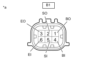
*a Component without harness connected
(Front Corner Ultrasonic Sensor LH)
Measure the resistance according to the value(s) in the table below.
Standard Resistance Tester Connection Condition Specified Condition B1-4 (BI) - B1-6 (EI) Always 10 kΩ or higher B1-4 (BI) - B1-1 (BO) Always Below 1 Ω B1-5 (SI) - B1-2 (SO) Always Below 30 Ω B1-6 (EI) - B1-3 (EO) Always Below 1 Ω Result Proceed to OK NG
NG
REPLACE FRONT CORNER ULTRASONIC SENSOR LH Click here
OK
-
-
INSPECT FRONT CENTER ULTRASONIC SENSOR LH
-
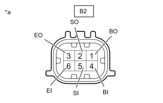
*a Component without harness connected
(Front Center Ultrasonic Sensor LH)
Measure the resistance according to the value(s) in the table below.
Standard Resistance Tester Connection Condition Specified Condition B2-4 (BI) - B2-6 (EI) Always 10 kΩ or higher B2-4 (BI) - B2-1 (BO) Always Below 1 Ω B2-5 (SI) - B2-2 (SO) Always Below 30 Ω B2-6 (EI) - B2-3 (EO) Always Below 1 Ω Result Proceed to OK NG
NG
REPLACE FRONT CENTER ULTRASONIC SENSOR LH Click here
OK
-
-
INSPECT FRONT CENTER ULTRASONIC SENSOR RH
-
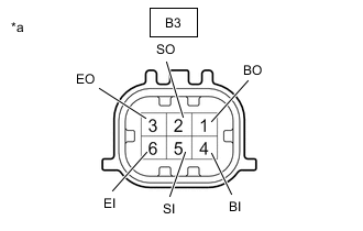
*a Component without harness connected
(Front Center Ultrasonic Sensor RH)
Measure the resistance according to the value(s) in the table below.
Standard Resistance Tester Connection Condition Specified Condition B3-4 (BI) - B3-6 (EI) Always 10 kΩ or higher B3-4 (BI) - B3-1 (BO) Always Below 1 Ω B3-5 (SI) - B3-2 (SO) Always Below 30 Ω B3-6 (EI) - B3-3 (EO) Always Below 1 Ω Result Proceed to OK NG
NG
REPLACE FRONT CENTER ULTRASONIC SENSOR RH Click here
OK
-
-
INSPECT FRONT CORNER ULTRASONIC SENSOR RH
-
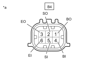
*a Component without harness connected
(Front Corner Ultrasonic Sensor RH)
Measure the resistance according to the value(s) in the table below.
Standard Resistance Tester Connection Condition Specified Condition B4-4(BI) - B4-6(EI) Always 10 kΩ or higher B4-4(BI) - B4 -1(BO) Always Below 1 Ω B4-5(SI) - B4 -2(SO) Always Below 30 Ω B4-6(EI) - B4 -3(EO) Always Below 1 Ω Result Proceed to OK NG
NG
REPLACE FRONT CORNER ULTRASONIC SENSOR RH Click here
OK
-
-
REPLACE FRONT CORNER ULTRASONIC SENSOR LH
Tech Tips
Result Proceed to NEXT
NEXT
-
CLEAR DTC
-
Clear the DTCs.
Body Electrical > IPA/ICS/Clearance Sonar > Clear DTCsResult Proceed to NEXT
NEXT
-
-
CHECK DTC OUTPUT (C1AEC)
-
Recheck for DTCs and check if the same DTC is output again.
Body Electrical > IPA/ICS/Clearance Sonar > Trouble CodesResult Result Proceed to C1AEC is output A C1AEC is not output B
B
END (FRONT CORNER ULTRASONIC SENSOR LH WAS DEFECTIVE)
A
-
-
REPLACE FRONT CENTER ULTRASONIC SENSOR LH
Tech Tips
Result Proceed to NEXT
NEXT
-
CLEAR DTC
-
Clear the DTCs.
Body Electrical > IPA/ICS/Clearance Sonar > Clear DTCsResult Proceed to NEXT
NEXT
-
-
CHECK DTC OUTPUT (C1AEC)
-
Recheck for DTCs and check if the same DTC is output again.
Body Electrical > IPA/ICS/Clearance Sonar > Trouble CodesResult Result Proceed to C1AEC is output A C1AEC is not output B
B
END (FRONT CENTER ULTRASONIC SENSOR LH WAS DEFECTIVE)
A
-
-
REPLACE FRONT CENTER ULTRASONIC SENSOR RH
Tech Tips
Result Proceed to NEXT
NEXT
-
CLEAR DTC
-
Clear the DTCs.
Body Electrical > IPA/ICS/Clearance Sonar > Clear DTCsResult Proceed to NEXT
NEXT
-
-
CHECK DTC OUTPUT (C1AEC)
-
Recheck for DTCs and check if the same DTC is output again.
Body Electrical > IPA/ICS/Clearance Sonar > Trouble CodesResult Result Proceed to C1AEC is output A C1AEC is not output B
B
END (FRONT CENTER ULTRASONIC SENSOR RH WAS DEFECTIVE)
A
-
-
REPLACE FRONT CORNER ULTRASONIC SENSOR RH
Tech Tips
Result Proceed to NEXT
NEXT
-
CLEAR DTC
-
Clear the DTCs.
Body Electrical > IPA/ICS/Clearance Sonar > Clear DTCsResult Proceed to NEXT
NEXT
-
-
CHECK DTC OUTPUT (C1AEC)
-
Check for DTCs.
Body Electrical > IPA/ICS/Clearance Sonar > Trouble CodesResult Result Proceed to C1AEC is output A C1AEC is not output B
A
REPLACE CLEARANCE WARNING ECU ASSEMBLY Click here
B
END (FRONT CORNER ULTRASONIC SENSOR RH WAS DEFECTIVE)
-