INTELLIGENT CLEARANCE SONAR SYSTEM SYSTEM DESCRIPTION
-
FUNCTION OF COMPONENTS
-
The intelligent clearance sonar system consists of the following components:
Component Function Clearance Warning ECU Assembly
-
Sends the drive force request signals and control status signals to the hybrid vehicle control ECU and skid control ECU.
-
Sends the multi-information display request signals and ICS OFF indicator light illumination request signals to the meter circuit plate.
-
Determines the distance between an obstruction and the vehicle based on the signals from the front center ultrasonic sensor, front corner ultrasonic sensor, rear center ultrasonic sensor and rear corner ultrasonic sensor.
-
Sounds the No. 1 clearance warning buzzer and No. 2 clearance warning buzzer in accordance with the control status.
Steering Pad Switch Assembly
- Multi-information Switch
Enables, disables or cuts off the operation of the intelligent clearance sonar system by transmitting the switch operation signal to the meter circuit plate. ECM Sends the engine speed signal to the clearance warning ECU assembly via CAN communication. Hybrid Vehicle Control ECU
-
Sends the accelerator pedal opening angle signal, shift status signal and drive force signal to the clearance warning ECU assembly via CAN communication.
-
Receives the drive force request signals and control status signals from the clearance warning ECU assembly via CAN communication.
Meter Circuit Plate
- Multi-information Display
- ICS OFF Indicator
- Meter buzzer
-
Sends the vehicle speed signal to the clearance warning ECU assembly via CAN communication.
-
Receives information from ultrasonic sensors via the clearance warning ECU assembly and displays it on the multi-information display.
-
Receives the multi-information display request signals via CAN communication and displays the control status of the intelligent clearance sonar system on the multi-information display.
-
Illuminates the ICS OFF indicator light when the intelligent clearance sonar system is off and blinks it when the intelligent clearance sonar system is malfunctioning.
-
Sends the intelligent clearance sonar system on/off signal to the clearance warning ECU assembly via CAN communication. The intelligent clearance sonar system can be turned on or off using the steering pad switch assembly.
-
Sounds the meter buzzer when the intelligent clearance sonar system is operating or malfunctioning.
Combination Meter Mirror ECU* Displays the control status of the intelligent clearance sonar system based on the signals received from the clearance warning ECU assembly via CAN communication. Stop Light Switch Assembly Detects if the brake pedal is depressed and outputs a signal to the skid control ECU. Skid Control ECU
-
Sends the master cylinder pressure signal and wheel speed signals to the clearance warning ECU assembly via CAN communication.
-
Receives the drive force request signal and control status signal from the clearance warning ECU assembly via CAN communication.
Steering Sensor Sends the steering angle signal to the clearance warning ECU assembly via CAN communication. Airbag ECU Assembly Sends the yaw rate and acceleration sensor (airbag ECU assembly) signal to the clearance warning ECU assembly via CAN communication.
-
Front Speed Sensor (LH/RH)
-
Rear Axle Hub and Bearing Assembly (LH/RH)
- Rear Speed Sensor (LH/RH)
Sends the wheel speed signals to the skid control ECU.
-
Shift Lever Position Sensor
-
P Position Switch (Transmission Shift Main Switch)
Sends the shift state signal to the hybrid vehicle control ECU.
-
Front Center Ultrasonic Sensor (LH/RH)
-
Front Corner Ultrasonic Sensor (LH/RH)
-
Rear Center Ultrasonic Sensor (LH/RH)
-
Rear Corner Ultrasonic Sensor (LH/RH)
Detects the distance between the vehicle and an obstacle.
-
No. 1 Clearance Warning Buzzer
-
No. 2 Clearance Warning Buzzer
Sounds upon receiving signals from the Clearance Warning ECU Assembly. Accelerator Pedal Sensor Assembly Sends the accelerator pedal opening angle signal to the hybrid vehicle control ECU. Main Body ECU (Multiplex Network Body ECU) Sends the driver seat belt signal to the clearance warning ECU assembly. Air Conditioning Amplifier Assembly Sends the ambient temperature signal to the clearance warning ECU assembly.
-
*: w/ Headup Display System
-
-
-
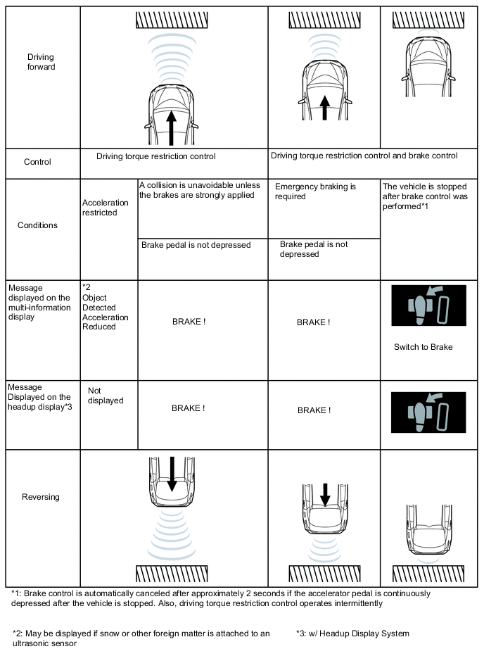
OPERATION CONDITIONS (Intelligent Clearance Sonar System)
-
Driving torque restriction control
-
Initiation Condition (When all of the following conditions are met, the driving torque restriction control is performed.)
-
The intelligent clearance sonar system is turned on.
-
An obstruction is detected by an ultrasonic sensor.
-
The vehicle speed is 15 km/h (9 mph) or less.
-
Collision is avoidable if emergency braking is performed by the driver.
-
-
Cancellation Condition (When any of the following conditions are met, driving torque restriction control is cancelled.)
-
The intelligent clearance sonar system is turned off.
-
No obstruction is detected by the ultrasonic sensors.
-
A possible collision is avoided.
-
-
-
Brake Control
-
Initiation Condition (When all of the following conditions are met, brake control is performed.)
-
Driving torque restriction control is performed.
-
A collision is likely even if emergency braking is performed by the driver.
-
-
Cancellation Condition (When any of the following conditions are met, driving torque restriction control is cancelled.)
-
The intelligent clearance sonar system is turned off.
-
The brake pedal is depressed after the vehicle is stopped by brake control.
-
Approximately 2 seconds have elapsed since the vehicle was stopped by brake control.
-
No obstruction is detected by the ultrasonic sensors.
-
-
-
Others
-
When brake control is performed, the intelligent clearance sonar system turns off automatically. The intelligent clearance sonar system turns on again when no obstructions are detected by the ultrasonic sensors, the shift lever is moved to reverse (R) with drive (D) selected or is moved to drive (D) with reverse (R) selected, the engine switch is turned off and then turned on (IG), or by using settings screen on the multi-information display.
Figure 1. Intelligent clearance sonar system operation
-
-
-
CASES OF UNNECESSARY INTELLIGENT CLEARANCE SONAR SYSTEM OPERATION
-
In the following situations, the intelligent clearance sonar system may operate even when there is no possibility of a collision:
-
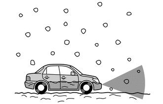
Environmental influence
-
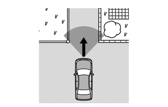
There is an obstacle on the shoulder of the road (when the vehicle is driven in a narrow tunnel, on a narrow bridge or on a narrow road).
-
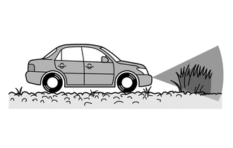
The vehicle is being driven on grass or a gravel road.
-
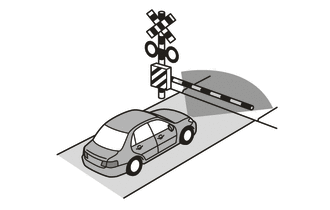
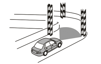
The vehicle is driven toward a banner or flag, a low-hanging branch or a boom barrier (such as those used at railroad crossings, toll gates and parking lots).
Tech Tips
Even if the intelligent clearance sonar system operates while on a railroad crossing, brake control will be automatically be canceled after approximately 2 seconds. Brake control can also be canceled by depressing the brake pedal. After brake control is canceled, depress the accelerator pedal to drive out of the railroad crossing.
-
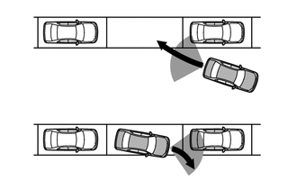
The vehicle is close to other vehicles while being parallel parked.
-
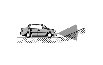
The vehicle is being driven on a steep slope.
-
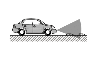
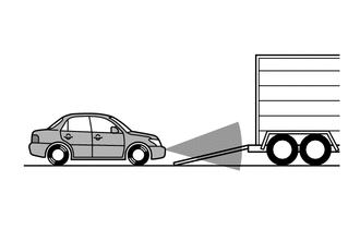
There are objects located lower than the ultrasonic sensors.
-
The vehicle is being driven on a narrow road.
-
There is a rut or hole in the surface of the road.
-
When the vehicle is driven on a metal cover (grating), such as those used for drainage ditches.
-
-
Influence from the weather
-
In severe weather such as fog, snow or a sandstorm.
-
Foreign matter such as snow, ice or mud is attached to an ultrasonic sensor. (The system returns to normal when the foreign matter is removed.)
-
When there is a downpour, or water is splashing on the vehicle.
-
Water is covering an ultrasonic sensor due to a flooded road.
-
-
Influence from other ultrasonic waves
-
When ultrasonic waves are received from the horn or parking sonar system of another vehicle, a motorcycle engine, or the air brakes of a large vehicle.
-
Electronic components such as a backlit license plate (especially fluorescent types), fog lights, a fender pole or a wireless antenna are installed near an ultrasonic sensor.
-
-
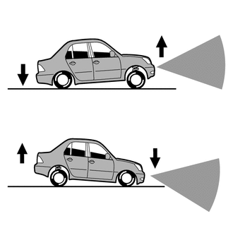
Changes in the vehicle.
-
The height of the vehicle has drastically changed due to loading (the nose tilts up or down).
-
The vehicle is significantly tilted.
-
An ultrasonic sensor is misaligned due to a collision, etc.
-
-
Others
-
The vehicle is being loaded onto a ship, truck or other transport vessel.
-
The vehicle is being operated on a drum tester such as a speedometer tester, brake/speedometer combination tester or chassis dynamometer.
-
When the vehicle is being towed.
-
-
-
-
MULTI-INFORMATION DISPLAY AND HEADUP DISPLAY (w/ Headup Display System)
-
Intelligent clearance sonar system display
-
The intelligent clearance sonar system uses the multi-information display in the meter circuit plate, the combination meter mirror ECU and ICS OFF indicator light to indicate the operation status of the system.
-
-
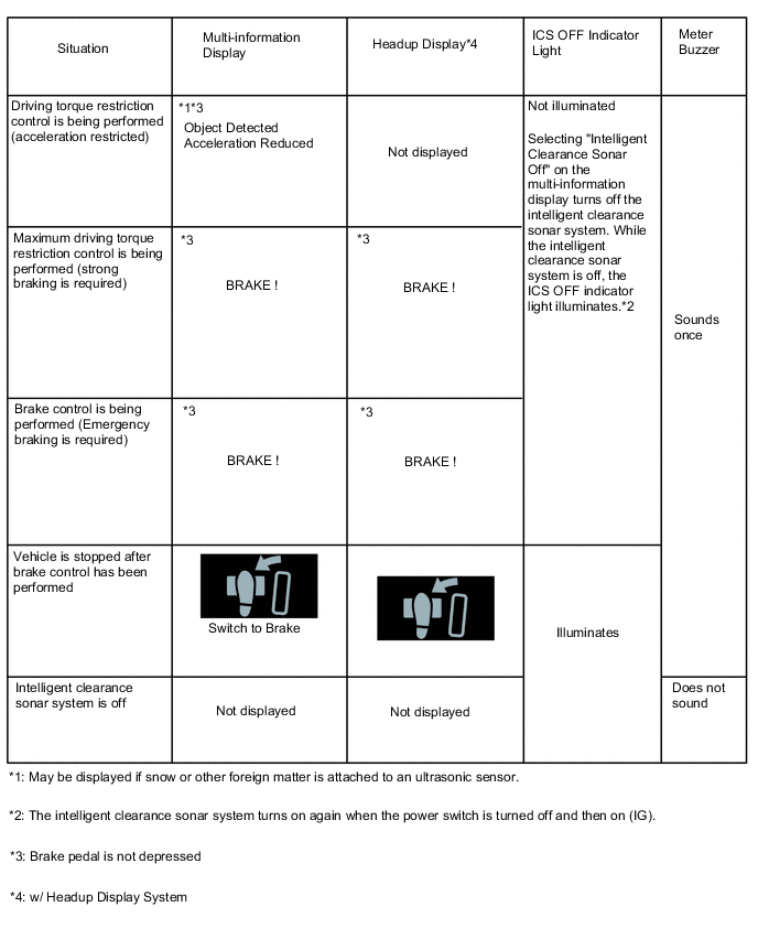
Intelligent clearance sonar system operation status display
-
When the operation conditions are met, the clearance warning ECU assembly sends display or illumination request signals to the meter circuit plate, combination meter mirror ECU and ICS OFF indicator light. The clearance warning ECU assembly also sends buzzer sound request signals to the meter circuit plate.
-
-
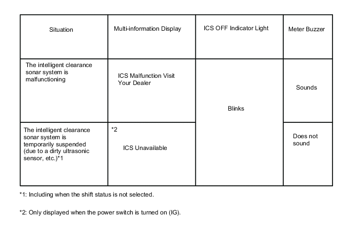
Intelligent clearance sonar system warning display
-
When operation of the intelligent clearance sonar system is temporarily suspended due to a malfunction or dirty ultrasonic sensor, a message is displayed on the multi-information display in the meter circuit plate, the ICS OFF indicator light blinks and the buzzer sounds.
-
-
Intelligent clearance sonar system off display
-
When the intelligent clearance sonar system is off, the ICS OFF indicator light illuminates.
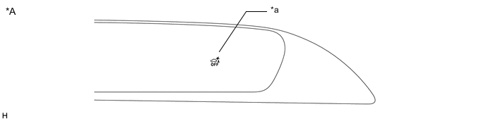
*A for LHD - - *a ICS OFF Indicator - - 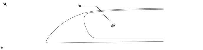
*A for RHD - - *a ICS OFF Indicator - - -
-