TELEMATICS SYSTEM, Diagnostic DTC:B1573, B15CB
| DTC Code | DTC Name |
|---|---|
| B1573 | Disconnect/Short in Telephone Antenna Circuit |
| B15CB | Telephone Antenna Disconnected |
DESCRIPTION
These DTCs are stored when a malfunction occurs in the roof antenna assembly.
| DTC No. | Detection Item | DTC Detection Condition | Trouble Area |
|---|---|---|---|
| B1573 | Disconnect/Short in Telephone Antenna Circuit | Roof antenna assembly impedance (Ω) is lower than the malfunction threshold for 20 seconds when the power switch is on (IG). (Short circuit) |
|
| B15CB | Telephone Antenna Disconnected | Roof antenna assembly impedance (Ω) is higher than the malfunction threshold for 20 seconds when the power switch is on (IG). (Open circuit) |
|
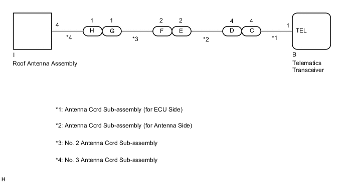
WIRING DIAGRAM
CAUTION / NOTICE / HINT
Note
Depending on the parts that are replaced during vehicle inspection or maintenance, performing initialization, registration or calibration may be needed. Refer to Registration for Telematics System.
PROCEDURE
-
CHECK DTC
-
Turn the power switch off.
-
Connect the GTS to the DLC3.
-
Turn the power switch on (IG) and wait for 20 seconds.
-
Turn the GTS on.
-
Check for DTCs and check that no DTCs are output.
Body Electrical > Telematics > Trouble CodesOK No DTCs are output. Result Proceed to OK NG
OK 
USE SIMULATION METHOD TO CHECK Click here
NG 
-
-
INSPECT ROOF ANTENNA ASSEMBLY
-
Remove the roof antenna assembly.
-
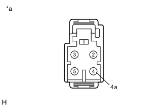
*a Component without harness connected
(Roof Antenna Assembly)
Measure the resistance according to the value(s) in the table below.
Standard Resistance Tester Connection Condition Specified Condition 4 - 4a Always 4 to 11 kΩ Result Proceed to OK NG
NG
REPLACE ROOF ANTENNA ASSEMBLY Click here
OK
-
-
INSPECT NO. 3 ANTENNA CORD SUB-ASSEMBLY
-
Remove the No. 3 antenna cord sub-assembly.
-
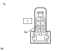
*a Component without harness connected
(No. 3 Antenna Cord Sub-assembly)
*a Component without harness connected
(No. 3 Antenna Cord Sub-assembly)
Measure the resistance according to the value(s) in the table below.
Standard Resistance Tester Connection Condition Specified Condition I-4 - H-1 Always Below 1 Ω I-4a - H-1a Always Below 1 Ω I-4 or H-1 - Body ground Always 10 kΩ or higher I-4a or H-1a - Body ground Always 10 kΩ or higher Result Proceed to OK NG
NG
REPLACE NO. 3 ANTENNA CORD SUB-ASSEMBLY Click here
OK
-
-
INSPECT NO. 2 ANTENNA CORD SUB-ASSEMBLY
-
Remove the No. 2 antenna cord sub-assembly.
-
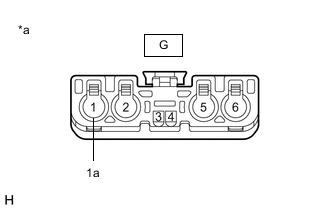
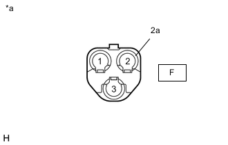
*a Component without harness connected
(No. 2 Antenna Cord Sub-assembly)
*a Component without harness connected
(No. 2 Antenna Cord Sub-assembly)
Measure the resistance according to the value(s) in the table below.
Standard Resistance Tester Connection Condition Specified Condition G-1 - F-2 Always Below 1 Ω G-1a - F-2a Always Below 1 Ω G-1 or F-2 - Body ground Always 10 kΩ or higher G-1a or F-2a - Body ground Always 10 kΩ or higher Result Proceed to OK NG
NG
REPLACE NO. 2 ANTENNA CORD SUB-ASSEMBLY Click here
OK
-
-
INSPECT ANTENNA CORD SUB-ASSEMBLY (for Antenna Side)
-
Remove the antenna cord sub-assembly (for Antenna Side).
-
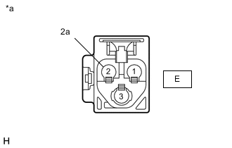
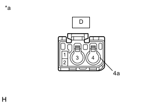
*a Component without harness connected
(Antenna Cord Sub-assembly (for Antenna Side))
*a Component without harness connected
(Antenna Cord Sub-assembly (for Antenna Side))
Measure the resistance according to the value(s) in the table below.
Standard Resistance Tester Connection Condition Specified Condition E-2 - D-4 Always Below 1 Ω E-2a - D-4a Always Below 1 Ω E-2 or D-4 - Body ground Always 10 kΩ or higher E-2a or D-4a - Body ground Always 10 kΩ or higher Result Proceed to OK NG
NG
REPLACE ANTENNA CORD SUB-ASSEMBLY (for Antenna Side) Click here
OK
-
-
INSPECT ANTENNA CORD SUB-ASSEMBLY (for ECU Side)
-
Remove the antenna cord sub-assembly (for ECU Side).
-
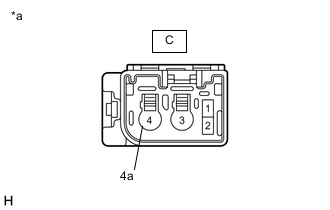
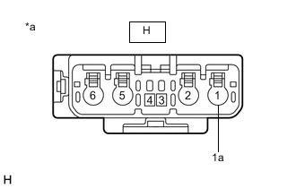
*a Component without harness connected
(Antenna Cord Sub-assembly (for ECU Side))
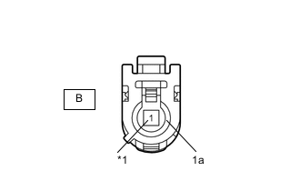
*1 TEL *a Component without harness connected
(Antenna Cord Sub-assembly (for ECU Side))
Measure the resistance according to the value(s) in the table below.
Standard Resistance Tester Connection Condition Specified Condition C-4 - B-1 (TEL) Always Below 1 Ω C-4a - B-1a Always Below 1 Ω C-4 or B-1 (TEL) - Body ground Always 10 kΩ or higher C-4a or B-1a - Body ground Always 10 kΩ or higher Result Proceed to OK NG
NG
REPLACE ANTENNA CORD SUB-ASSEMBLY (for ECU Side) Click here
OK
-
-
REPLACE TELEMATICS TRANSCEIVER
-
Replace the telematics transceiver with a new one.
Result Proceed to NEXT
NEXT
PERFORM REGISTRATION Click here
-