EXHAUST PIPE INSTALLATION
PROCEDURE
-
INSTALL FRONT EXHAUST PIPE ASSEMBLY (TWC: Rear Catalyst)
-
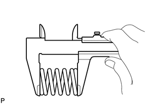
Using a vernier caliper, measure the free length of the compression springs.
Standard Length 43.0 mm (1.69 in.) Minimum Free Length 41.5 mm (1.63 in.) If the free length is less than the minimum, replace the compression spring.
-
Temporarily install a new exhaust pipe gasket to the exhaust manifold (TWC: Front Catalyst).
-
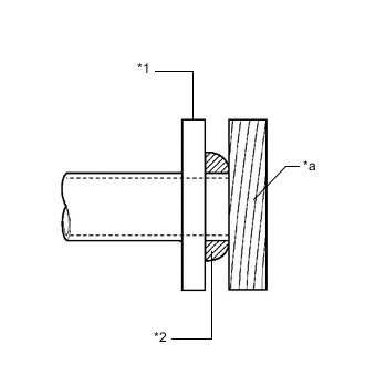
*1 Exhaust Manifold (TWC: Front Catalyst) *2 Exhaust Pipe Gasket *a Wooden Block Using a plastic hammer and wooden block, tap in the exhaust pipe gasket until its surface is flush with the exhaust manifold (TWC: Front Catalyst).
Note
-
Be careful with the installation direction of the exhaust pipe gasket.
-
Do not reuse the exhaust pipe gasket.
-
Do not damage the exhaust pipe gasket.
-
Do not push in the exhaust pipe gasket by using the exhaust pipes when connecting them.
-
-
Connect the front exhaust pipe assembly (TWC: Rear Catalyst) to the 2 exhaust pipe supports.
-
Install the front exhaust pipe assembly (TWC: Rear Catalyst) to the exhaust manifold (TWC: Front Catalyst) with the 2 compression springs and 2 bolts.
- Torque:
- 43 N*m { 438 kgf*cm, 32 ft.*lbf }
Tech Tips
After installation, check that the space between the flanges of the exhaust manifold (TWC: Front Catalyst) and front exhaust pipe assembly (TWC: Rear Catalyst) is consistent front-to-rear and left-to-right.
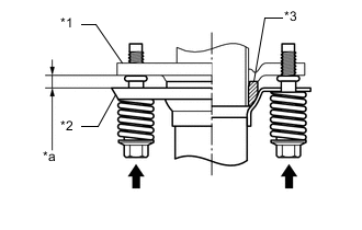
*1 Exhaust Manifold (TWC: Front Catalyst) *2 Front Exhaust Pipe Assembly (TWC: Rear Catalyst) *3 Exhaust Pipe Gasket *a Space between Flanges: 8.5 mm (0.335 in.) -
w/ Exhaust Heat Recirculation System:
-
Connect the outlet heater water hose B and outlet heater water hose C to the No. 2 outlet water pipe and inlet water pipe and slide the 2 clips to secure them.
Note
When installing the outlet heater water hose B and outlet heater water hose C, ensure that the exhaust heat recirculation system is filled with coolant. Otherwise, the engine water pump assembly may be damaged.
-
-
-
INSTALL TAIL EXHAUST PIPE ASSEMBLY
-
Using a vernier caliper, measure the free length of the compression springs.
Standard Length 40 mm (1.57 in.) Minimum Free Length 38.5 mm (1.52 in.) If the free length is less than the minimum, replace the compression spring.
-
Temporarily install a new exhaust pipe gasket to the front exhaust pipe assembly (TWC: Rear Catalyst).
-
*1 Front Exhaust Pipe Assembly (TWC: Rear Catalyst) *2 Exhaust Pipe Gasket *a Wooden Block Using a plastic hammer and wooden block, tap in the exhaust pipe gasket until its surface is flush with the front exhaust pipe assembly (TWC: Rear Catalyst).
Note
-
Be careful with the installation direction of the exhaust pipe gasket.
-
Do not reuse the exhaust pipe gasket.
-
Do not damage the exhaust pipe gasket.
-
Do not push in the exhaust pipe gasket by using the exhaust pipes when connecting them.
-
-
Connect the tail exhaust pipe assembly to the 4 exhaust pipe supports.
-
Install the tail exhaust pipe assembly to the front exhaust pipe assembly (TWC: Rear Catalyst) with the 2 bolts and 2 compression springs.
- Torque:
- 43 N*m { 438 kgf*cm, 32 ft.*lbf }
Tech Tips
After installation, check that the space between the flanges of the tail exhaust pipe assembly and front exhaust pipe assembly (TWC: Rear Catalyst) is consistent front-to-rear and left-to-right.
*1 Front Exhaust Pipe Assembly (TWC: Rear Catalyst) *2 Tail Exhaust Pipe Assembly *3 Exhaust Pipe Gasket *a Space between Flanges: 6.5 mm (0.256 in.)
-
-
INSTALL HEATED OXYGEN SENSOR
-
ADD ENGINE COOLANT (w/ Exhaust Heat Recirculation System)
-
INSPECT FOR COOLANT LEAK (w/ Exhaust Heat Recirculation System)
-
INSPECT FOR EXHAUST GAS LEAK
If gas is leaking, tighten the areas necessary to stop the leak. Replace damaged parts as necessary.
-
Perform Inspection After Repair after repairing an exhaust gas leak.
-
w/ Canister Pump Module:
-
w/o Canister Pump Module:
-
-
-
INSTALL FRONT CENTER FLOOR BRACE
-
Install the 2 front center floor braces to the vehicle body with the 8 bolts.
- Torque:
- 29 N*m { 296 kgf*cm, 21 ft.*lbf }
-
-
INSTALL FRONT FLOOR COVER LH
-
INSTALL FRONT FLOOR COVER RH
-
INSTALL REAR MOTOR UNDER COVER LH (w/ Exhaust Heat Recirculation System)