FUEL SENDER GAUGE ASSEMBLY(w/ Canister Pump Module) REMOVAL
CAUTION / NOTICE / HINT
The necessary procedures (adjustment, calibration, initialization or registration) that must be performed after parts are removed and installed, or replaced during fuel sender gauge assembly removal/installation are shown below.
| Replaced Part or Performed Procedure | Necessary Procedure | Effect/Inoperative Function when Necessary Procedure not Performed | Link |
|---|---|---|---|
| Auxiliary battery terminal is disconnected/reconnected | Memorize steering angle neutral point | Lane departure alert system (w/ Steering Control) | |
| Intelligent clearance sonar system*1 | |||
| Simple intelligent parking assist system*1 | |||
| Pre-crash safety system | |||
| Parking assist monitor system | |||
| Initialize back door lock | Power door lock control system |
*1: When performing learning using the GTS.
PROCEDURE
-
REMOVE FUEL SUCTION TUBE WITH PUMP AND GAUGE ASSEMBLY
-
REMOVE FUEL SENDER GAUGE ASSEMBLY
-
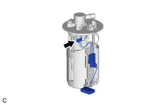
Disconnect the fuel sender gauge assembly connector.
-
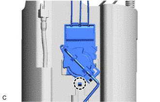
Disengage the claw to remove the fuel sender gauge assembly from the fuel suction tube with pump and gauge assembly.
Note
Be careful not to bend the arm of the fuel sender gauge assembly.
-