REAR CRANKSHAFT OIL SEAL REMOVAL

CAUTION / NOTICE / HINT
The necessary procedures (adjustment, calibration, initialization, or registration) that must be performed after parts are removed and installed, or replaced during rear crankshaft oil seal removal/installation are shown below.
| Replaced Part or Performed Procedure | Necessary Procedure | Effect/Inoperative Function when Necessary Procedure not Performed | Link |
|---|---|---|---|
| Auxiliary battery terminal is disconnected/reconnected | Memorize steering angle neutral point | Lane departure alert system (w/ Steering Control) | |
| Intelligent clearance sonar system*1 | |||
| Simple intelligent parking assist system*1 | |||
| Pre-crash safety system | |||
| Parking assist monitor system | |||
| Initialize back door lock | Power door lock control system | ||
| Replacement of inverter with converter assembly | Resolver learning |
|
|
for SFI system (w/ Canister Pump Module) |
Perform Vehicle Identification Number (VIN) registration | MIL comes on | |
for SFI system (w/o Canister Pump Module) |
Perform Vehicle Identification Number (VIN) or frame number registration | ||
for SFI system (w/ Canister Pump Module) |
Inspection After Repair |
|
|
for SFI system (w/o Canister Pump Module) |
Inspection After Repair |
|
|
| Suspension, tires, etc. (The vehicle height changes because of suspension or tire replacement) |
|
|
|
| Rear television camera assembly optical axis (Back camera position setting) | Parking assist monitor system | ||
| Initialize No. 1 headlight ECU sub-assembly LH | Automatic headlight beam level control system | ||
| Front wheel alignment adjustment |
|
|
|
| Replacement of hybrid vehicle transaxle assembly |
|
|
*1: When performing learning using the GTS.
PROCEDURE
-
REMOVE ENGINE ASSEMBLY
-
REMOVE TRANSMISSION INPUT DAMPER ASSEMBLY
-
Using height adjustment attachments and plate lift attachments, place the engine assembly on a flat level surface.
Note
-
Using height adjustment attachments and plate lift attachments, keep the engine assembly horizontal.
-
To prevent the oil pan sub-assembly from deforming, do not place any attachments under the oil pan sub-assembly of the engine assembly.
-
Using an engine sling device and engine lift, secure the engine assembly before servicing.
-
-
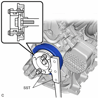
Using SST, hold the crankshaft pulley.
- SST
- 09213-58014 ( 91551-80840 )
- 09330-00021
-
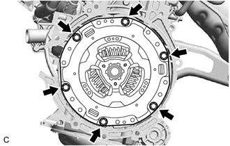
Remove the 6 bolts and transmission input damper assembly from the flywheel sub-assembly.
-
-
REMOVE FLYWHEEL SUB-ASSEMBLY
-
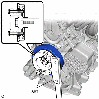
Using SST, hold the crankshaft pulley.
- SST
- 09213-58014 ( 91551-80840 )
- 09330-00021
-
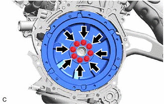
Remove the 8 bolts and flywheel sub-assembly from the crankshaft.
-
-
REMOVE REAR ENGINE OIL SEAL
-
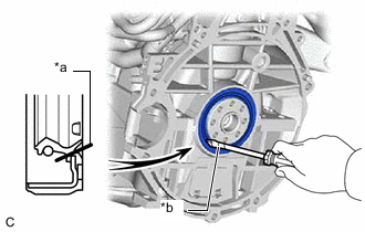
*a Cut Position *b Protective Tape Using a knife, cut through the lip of the rear engine oil seal.
-
Using a screwdriver with its tip wrapped with protective tape, pry out the rear engine oil seal.
Note
Be careful not to damage the crankshaft.
-