MOTOR GENERATOR CONTROL COMPUTER REMOVAL

CAUTION / NOTICE / HINT
The necessary procedures (adjustment, calibration, initialization, or registration) that must be performed after parts are removed and installed, or replaced during motor generator control ECU kit removal/installation are shown below.
| Replaced Part or Performed Procedure | Necessary Procedures | Effect/Inoperative Function when Necessary Procedure not Performed | Link |
|---|---|---|---|
| Auxiliary battery terminal is disconnected/reconnected | Memorize steering angle neutral point | Lane departure alert system (w/ Steering Control) | |
| Intelligent clearance sonar system*1 | |||
| Simple intelligent parking assist system*1 | |||
| Pre-crash safety system | |||
| Parking assist monitor system | |||
| Initialize back door lock | Power door lock control system | ||
| Replacement of inverter with converter assembly | Resolver learning |
|
|
for SFI system (w/ Canister Pump Module) |
Perform Vehicle Identification Number (VIN) registration | MIL comes on | |
for SFI system (w/o Canister Pump Module) |
Perform Vehicle Identification Number (VIN) or frame number registration |
Click here Click here
CAUTION:
-
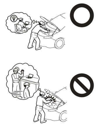
Orange wire harnesses and connectors indicate high-voltage circuits. To prevent electric shock, always follow the procedure described in the repair manual.
-
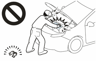
To prevent electric shock, wear insulated gloves when working on wire harnesses and components of the high voltage system.
Note
-
If metal shavings are created when bolts are removed from the inverter with converter assembly, remove them using tape or equivalent.
-
Use non-residue type tape.
Tech Tips
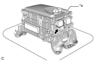
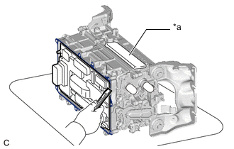
When replacing the motor generator control computer kit, make sure to check the part number label on the inverter upper cover and replace the motor generator control computer kit with the appropriate part.
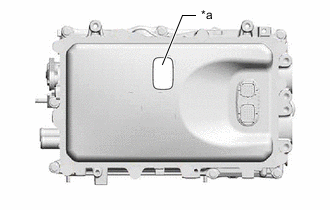
| *a | Part Number Label |
| Part Number | Motor Generator Control ECU Kit Number |
|---|---|
| G9200-47240 G9200-47260 |
04899-47100(Number of Connectors:21) |
If the part number is not listed above, refer to the parts catalog.
PROCEDURE
-
REMOVE INVERTER WITH CONVERTER ASSEMBLY
-
REMOVE WIRE HARNESS CLAMP BRACKET
-
VERIFY THAT VOLTAGE OF INVERTER WITH CONVERTER IS 0 V
CAUTION:
Wear insulating gloves.
Note
Do not allow any foreign matter or water to enter the inverter with converter assembly.
-
*a Tape Remove the protective tape from the HV floor under wire opening.
-
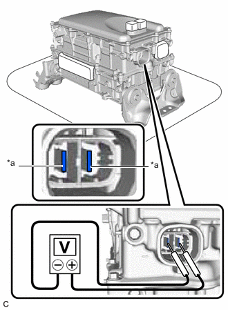
*a Voltage Measurement Position Using a voltmeter, measure the voltage between the high voltage cable connector terminals.
Standard voltage 0V Tech Tips
-
Use measuring range of DC 750 V or more on the voltmeter.
-
If it is confirmed that high-voltage is not being applied to the inverter with converter assembly, the following procedures can be performed without using insulated tools or gloves.
-
-
Apply protective tape to the area that was exposed.
Note
Use non-residue type tape.
-
-
CLEAN INVERTER WITH CONVERTER ASSEMBLY
-
Using a piece of cloth, clean the outside of the inverter with converter assembly and around the bolts.
Note
To prevent foreign matter from entering the inverter with converter assembly, make sure that the protective tape is not partially removed.
-
-
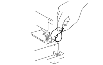
HOW TO PREVENT STATIC ELECTRICITY
- SST
- 09890-47010
Note
-
Static electricity should be eliminated when removing/installing the inverter with converter assembly.
-
Do not touch the electronic components of a circuit board.
-
Keep clothes away from electronic components.
-
Place the inverter with converter assembly and any removed electronic components on SST (antistatic mat).
-
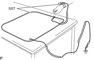
Wear an antistatic wrist strap.
-
Connect the ground clip of the antistatic mat securely to a ground point provided in the workshop or on a workbench (anchor bolt).
Tech Tips
If the ground clip cable is too short, use an extension cable.
-
Connect the ground clip of the antistatic wrist strap securely to the specified point of the antistatic mat.
-
When handling internal components of the inverter with converter assembly, use only antistatic gloves or bare hands to prevent damage from static electricity or the entry of foreign matter.
-
REMOVE INVERTER UPPER COVER
-
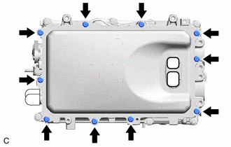
Remove the 10 bolts.
-
Using a screwdriver with its tip wrapped with protective tape, bend the 2 flanges of the inverter upper cover inward.
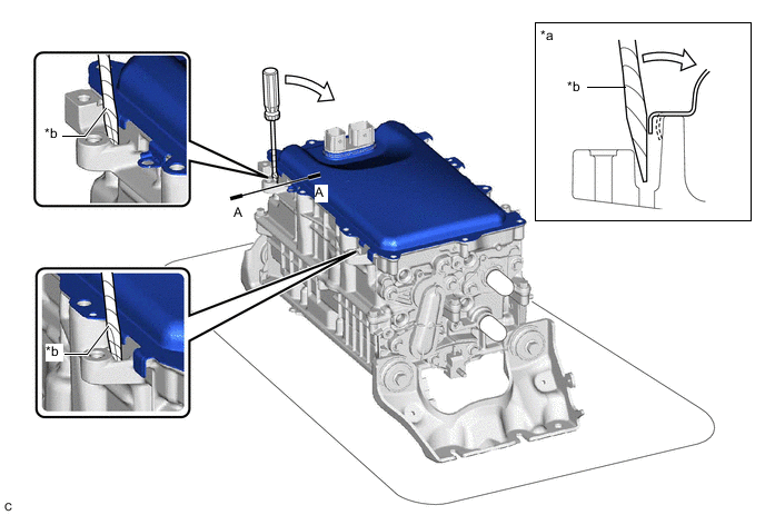
*a A-A Cross Section *b Protective Tape -
Using a screwdriver with its tip wrapped with protective tape, remove the inverter upper cover from the inverter with converter assembly.
*a Protective Tape - - Note
-
Do not damage the sealing surfaces of the inverter with converter assembly.
-
Do not touch or allow grease or oil to contact the sealing surfaces of the inverter with converter assembly.
-
Be careful not to damage the sealing surfaces of the inverter with converter assembly.
-
To prevent internal components of the inverter with converter assembly from being damaged, do not insert the screwdriver excessively.
-
-
-
REMOVE SEAL PACKING FROM INVERTER WITH CONVERTER ASSEMBLY
Note
-
Do not allow any removed seal packing to enter the inverter with converter assembly.
-
Do not touch the circuit board.
-
Do not allow any moisture to come into contact.
-
Using a finger, remove any seal packing that has seeped into the inverter with converter assembly.
Tech Tips
Make sure to remove any seal packing which has seeped toward the inside of inverter with converter assembly before installing the seal packing removal cover, otherwise the seal packing may be pushed into the inverter with converter assembly.
-
Break off the seal packing removal cover and scraper at each break off line.
-
Set the seal packing removal cover on the inverter with converter assembly and secure it by lightly pressing it at the 2 areas shown in the illustration.
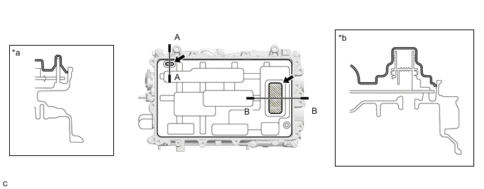
*a A-A Cross Section *b B-B Cross Section 
Push - - Note
Make sure that the seal packing removal cover is in secure contact with the inside surface of the inverter with converter assembly without any gaps.
-
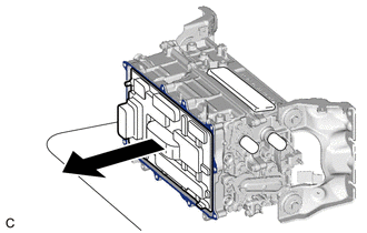
*a MG Connector Opening Place the inverter with converter assembly on its side on an antistatic mat as shown in the illustration.
Note
-
Make sure that the MG connector opening in the inverter with converter assembly is facing upward.
-
Make sure that the inverter with converter assembly is oriented correctly, otherwise seal packing may enter the inverter with converter assembly.
-
-
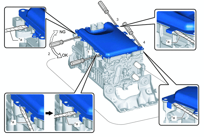
Using a scraper, remove any remaining seal packing from the inverter with converter assembly.
Note
-
It is not necessary to remove small amounts of seal packing which are not easily scraped off.
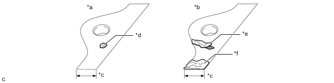
*a Correct *b Incorrect *c Width of Sealing Surface *d Difficult to Remove Seal Packing *e Peeled Off Seal Packing *f Seal Packing Remaining on Full Width of Sealing Surface -
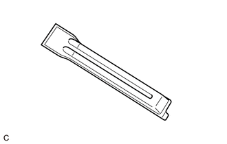
Make sure to use the scraper supplied with the seal packing removal cover.
Tech Tips
Use the small end of the scraper to remove seal packing from small areas such as bolt holes.
-
-
Using a clean piece of cloth, clean the sealing surfaces of the inverter with converter assembly.
Note
-
Do not use compressed air or a vacuum cleaner to clean the sealing surfaces of the inverter with converter assembly.
-
Do not use non-residue solvent to clean the sealing surfaces of the inverter with converter assembly.
-
-
Remove the seal packing removal cover.
Note
Make sure that the inverter with converter assembly is oriented correctly, otherwise seal packing may enter the inverter with converter assembly when removing the seal packing removal cover.
-
Check for and remove any foreign matter which has entered the inverter with converter assembly.
-
Set the inverter with converter assembly upright.
-
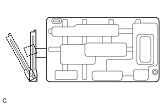
Clean the seal packing removal cover.
Tech Tips
As the seal packing removal cover will be reused, it is necessary to clean it to prevent foreign matter from entering the inverter with converter assembly and prevent damage.
-
-
REMOVE MOTOR GENERATOR CONTROL ECU KIT
CAUTION:
To prevent foreign matter from entering the inverter with converter assembly, once the seal packing removal cover has been removed, work cannot be suspended until the motor generator control ECU kit is reinstalled.
Note
-
Do not touch the circuit board.
-
Do not allow any foreign matter or water to enter the inverter with converter assembly.
-
Install the seal packing removal cover to the inverter with converter assembly.
Tech Tips
The seal packing removal cover is installed to help prevent the motor generator control computer kit from being damaged if a part or tool is dropped on it.
-
Install the 2 guide pins by hand at the positions shown in the illustration.
Note
Make sure that the guide pins are tightened securely.
-
Remove the seal packing removal cover.
-
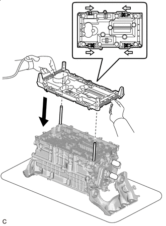

Unlock 
Rib Check that the 4 clips of the circuit board replacement jig are unlocked, and then while holding the circuit board replacement jig by the ribs, align it with the guide pins and set it on the inverter with converter assembly.
Tech Tips
Make sure that circuit board replacement jig is perfectly level with the sealing surface.
-
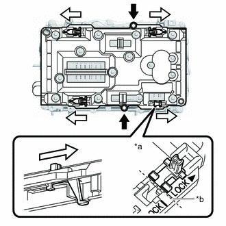
*a Locked *b Locked Position 
Bolt Lock Secure the circuit board replacement jig with 2 inverter upper cover installation bolts.
-
Lock the 4 clips as shown in the illustration to secure the circuit board replacement jig to the circuit board.
Note
When locking the clips of the circuit board replacement jig, do not apply excessive force to the clips, otherwise the circuit board replacement jig may be damaged.
Tech Tips
Make sure that the clips of the circuit board replacement jig are securely locked.
-
*a Part Number Label Check the part number label on the inverter upper cover.
Tech Tips
The number of vibration dampening connectors on the motor generator control ECU kit differs according to the part number.
Type Part Number Number of Vibration Dampening Connectors A for Inverter with Converter Assembly with Part Number
-
G9200-47240
G9200-47260
21 B for Inverter with Converter Assembly with Part Number Other Than
-
G9200-47240
G9200-47260
20 -
-
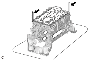
Type A:
-
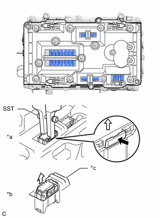
*a Connected Vibration Dampening Connector *b Disconnected Vibration Dampening Connector *c Stopper of The Circuit Board Replacement Jig Using SST, release the lock of each vibration dampening connector and raise the 21 vibration dampening connectors until they reach the stopper of the circuit board replacement jig.
- SST
- 09905-00040
Note
When disconnecting the vibration dampening connectors, release the lock of each connector with SST and then carefully lift the connector the specified amount.
Tech Tips
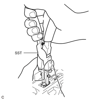
-
To prevent the vibration dampening connectors from being pulled up excessively, use both hands to raise them slowly as shown in the illustration.
-
The position of the lock will vary depending on the position of the vibration dampening connector. Refer to the arrows on the circuit board replacement jig.
-
-
Type B:
-
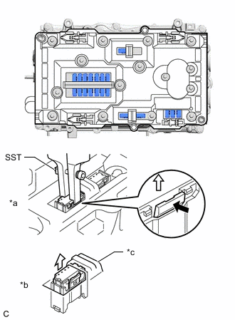
*a Connected Vibration Dampening Connector *b Disconnected Vibration Dampening Connector *c Stopper of The Circuit Board Replacement Jig Using SST, release the lock of each vibration dampening connector and raise the 20 vibration dampening connectors until they reach the stopper of the circuit board replacement jig.
- SST
- 09905-00040
Note
When disconnecting the vibration dampening connectors, release the lock of each connector with SST and then carefully lift the connector the specified amount.
Tech Tips
-
To prevent the vibration dampening connectors from being pulled up excessively, use both hands to raise them slowly as shown in the illustration.
-
The position of the lock will vary depending on the position of the vibration dampening connector. Refer to the arrows on the circuit board replacement jig.
-
-
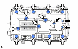
Bolt (A) Bolt (B) Remove the 3 bolts (A).
Tech Tips
If the bolts are difficult to remove from the circuit board replacement jig, use a magnet hand.
-
Remove the 12 bolts (B).
Tech Tips
If the bolts are difficult to remove from the circuit board replacement jig, use a magnet hand.
-
Remove the 2 inverter upper cover installation bolts.
-
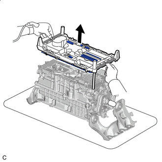
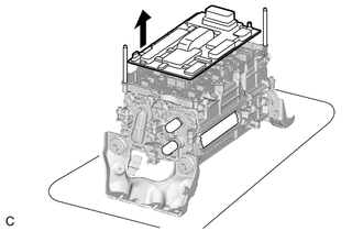
Rib While holding the circuit board replacement jig by the ribs, evenly lift the circuit board replacement jig and circuit board straight up and remove it.
-
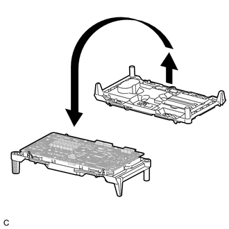
Place the circuit board replacement jig upside down on a clean workbench.
-
Check that the terminals of the inverter with converter assembly are not bent or damaged and that it is free of foreign matter.
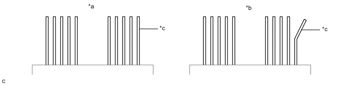
*a Correct *b Incorrect *c Terminal - - Note
-
Do not touch the terminals.
-
If any of the terminals are bent, replace the inverter with converter assembly with a new one. Do not attempt to repair the terminals.
-
-
Unlock the 4 circuit board replacement jig clips, and then while holding the sides of the circuit board or the top and bottom of the circuit board at the areas shown in the illustration, lift the circuit board to remove it from the circuit board replacement jig.
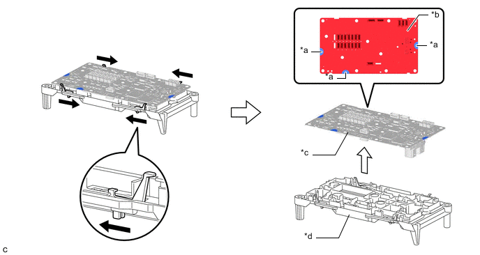
*a Hold here *b Do not hold here *c Circuit Board *d Circuit Board Replacement Jig Unlock - - Note
Be careful not to touch any part of the circuit board other than the specified areas.
-