HYBRID VEHICLE CONTROL ECU REMOVAL
CAUTION / NOTICE / HINT
The necessary procedures (adjustment, calibration, initialization, or registration) that must be performed after parts are removed and installed, or replaced during hybrid vehicle control ECU removal/installation are shown below.
| Replaced Part or Performed Procedure | Necessary Procedures | Effect/Inoperative Function when Necessary Procedure not Performed | Link |
|---|---|---|---|
| Auxiliary battery terminal is disconnected/reconnected | Memorize steering angle neutral point | Lane departure alert system (w/ Steering Control) | |
| Intelligent clearance sonar system*1 | |||
| Simple intelligent parking assist system*1 | |||
| Pre-crash safety system | |||
| Parking assist monitor system | |||
| Initialize back door lock | Power door lock control system | ||
| Replacement of hybrid vehicle control ECU | Perform code registration (Immobiliser system) |
|
See Service Bulletin for the registration method. |
| Clear DTCs (Vehicle proximity notification system)*2 | Vehicle proximity notification system |
*1: When performing learning using the GTS.
*2: w/ Vehicle Proximity Notification System
PROCEDURE
-
PRECAUTION
Note
-
After turning the power switch off, waiting time may be required before disconnecting the cable from the negative (-) auxiliary battery terminal. Therefore, make sure to read the disconnecting the cable from the negative (-) auxiliary battery terminal notices before proceeding with work.
-
Before replacing the hybrid vehicle control ECU, refer to Service Bulletin.
-
-
DISCONNECT CABLE FROM NEGATIVE AUXILIARY BATTERY TERMINAL
Note
When disconnecting the cable, some systems need to be initialized after the cable is reconnected.
-
REMOVE NO. 2 INSTRUMENT PANEL UNDER COVER SUB-ASSEMBLY
-
REMOVE GLOVE COMPARTMENT DOOR ASSEMBLY
-
REMOVE ECU INTEGRATION BOX RH (for LHD)
-
Disconnect each connector.
-
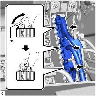
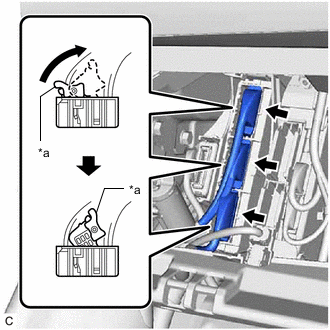
*a Lock Lever Move each lock lever as shown in the illustration and disconnect the 3 hybrid vehicle control ECU connectors.
-
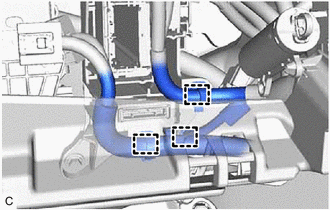
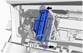
Disengage the 3 clamps.
-
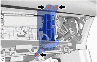
Remove the bolt, 2 nuts and ECU integration box RH.
-
-
REMOVE HYBRID VEHICLE CONTROL ECU (for LHD)
-
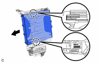
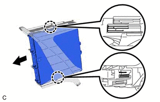
Disengage the 2 claws and remove the hybrid vehicle control ECU as shown in the illustration.
Note
-
If the ECU integration box is deformed or damaged, replace it.
-
Do not bend the 2 claws more than necessary.
-
-
-
REMOVE ECU INTEGRATION BOX LH (for RHD)
-
Disconnect each connector.
-
*a Lock Lever Move each lock lever as shown in the illustration and disconnect the 3 hybrid vehicle control ECU connectors.
-
Remove the bolt, nut and ECU integration box LH.
-
-
REMOVE HYBRID VEHICLE CONTROL ECU (for RHD)
-
Disengage the 2 claws and remove the hybrid vehicle control ECU as shown in the illustration.
Note
-
If the ECU integration box is deformed or damaged, replace it.
-
Do not bend the 2 claws more than necessary.
-
-