MOTOR GENERATOR CONTROL SYSTEM, Diagnostic DTC:P1CB7A2
| DTC Code | DTC Name |
|---|---|
| P1CB7A2 | Motor Generator System Voltage Low |
DTC SUMMARY
-
Malfunction Description
If the auxiliary battery is damaged, the back-up power supply supplies power for a certain time to discharge the high-voltage capacitor inside the inverter with converter assembly. If the back-up power supply function cannot operate for a certain amount of time, this will be judged as a malfunction and the master warning light will be illuminated.
Even if this DTC is stored, the vehicle can still be driven normally. Although the master warning light will be illuminated, a fail-safe function will not operate.
DESCRIPTION
| DTC No. | Detection Item | DTC Detection Condition | Trouble Area | MIL | Warning Indicate |
|---|---|---|---|---|---|
| P1CB7A2 | Motor Generator System Voltage Low | After the power supply to the IGCT relay is cut (the MG ECU is not operating), both of the following conditions are met for less than 3.5 seconds:
(2 trip detection logic) |
|
Does not come on | Master Warning Light: Comes on |
| DTC No. | Data List |
|---|---|
| P1CB7A2 |
|
CONFIRMATION DRIVING PATTERN
Tech Tips
After repair has been completed, clear the DTC and then check that the vehicle has returned to normal by performing the following All Readiness check procedure.
-
Connect the GTS to the DLC3.
-
Turn the power switch on (IG) and turn the GTS on.
-
Clear the DTCs (even if no DTCs are stored, perform the clear DTC procedure).
-
Turn the power switch off and wait for2 minutes or more.
-
Turn the power switch on (IG) and turn the GTS on.
-
Drive the vehicle at a speed of 15 km/h (9.3 mph) or more. (*1)
-
Warm the vehicle so that all of the following conditions are met: (*2)
-
The HV battery temperature is 15°C (59°F) or more.
-
Inverter coolant temperature is 20°C (68°F) or more.
-
Engine coolant temperature is 20°C (68°F) or more.
-
Intake air temperature is 20°C (68°F) or more.
-
Turn the power switch on (READY) and maintain the conditions above for 10 minutes or more. (*3)
Tech Tips
If the ambient temperature is low, depress the accelerator pedal and brake pedal with park (P) selected to start the engine and help maintain the conditions above.
-
Turn the power switch off and wait for 2 minutes or more.
-
Repeat steps (*1) through (*3).
-
Enter the following menus: Powertrain / Motor Generator / Utility / All Readiness.
-
Check the DTC judgment result.
Tech Tips
-
If the judgment result shows NORMAL, the system is normal.
-
If the judgment result shows ABNORMAL, the system has a malfunction.
-
If the judgment result shows INCOMPLETE or N/A, perform driving pattern again.
-
WIRING DIAGRAM
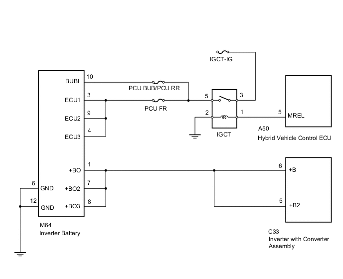
CAUTION / NOTICE / HINT
Tech Tips
After the power switch is turned off, even if the cable is disconnected from the negative (-) auxiliary battery terminal, voltage will continue to be supplied to terminal +B and terminal +B2 of the inverter with converter assembly by the inverter battery (backup power supply) for approximately 2 minutes.
PROCEDURE
-
CHECK AUXILIARY BATTERY TERMINAL (CONTACT PROBLEM)
-
Check the connection of the negative (-) and positive (+) auxiliary battery terminals.
OK The terminals are connected securely and there is no contact problem. Tech Tips
If performing a reproduction test, turn the power switch on (IG) and shake the wire harnesses vertically and horizontally before checking for DTCs.
Result Proceed to OK NG
NG 
CONNECT SECURELY Click here
OK 
-
-
CHECK GROUND WIRE CONNECTION CONDITION
-
Check the installation condition of the ground wires DA and DC.
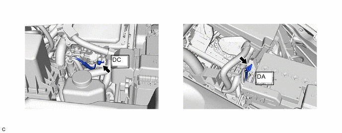
OK The ground wires DA and DC are securely installed. Tech Tips
If performing a reproduction test, turn the power switch on (IG) and shake the wire harnesses vertically and horizontally before checking for DTCs.
Result Proceed to OK NG
NG
CONNECT SECURELY Click here
OK
-
-
CHECK FUSIBLE LINK (BATT-MAIN)
-
Disconnect the cable from the negative (-) auxiliary battery terminal.
-
Disconnect the cable from the positive (+) auxiliary battery terminal.
-
Check the fusible link block assembly (BATT-MAIN) for improper installation.
OK The fusible link block assembly is installed securely and there is no contact problem. -
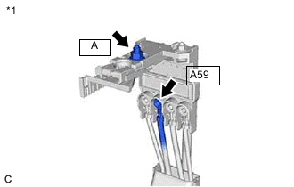
*1 Fusible Link Block Assembly Measure the resistance according to the value(s) in the table below.
Standard Resistance Tester Connection Condition Specified Condition A59-1 - A-1 (Positive (+) auxiliary battery terminal) Power switch off Below 1 Ω -
Reconnect the cable from the positive (+) auxiliary battery terminal.
-
Reconnect the cable from the negative (-) auxiliary battery terminal.
Result Proceed to OK NG
NG
REPAIR OR REPLACE MALFUNCTIONING PARTS Click here
OK
-
-
CHECK FUSE (IGCT-IG)
-
Check the IGCT-IG fuse for improper installation.
OK The fuse is installed securely. Tech Tips
If performing a reproduction test, turn the power switch on (IG) and gently vibrate the IGCT-IG fuse with a finger before checking for DTCs.
-
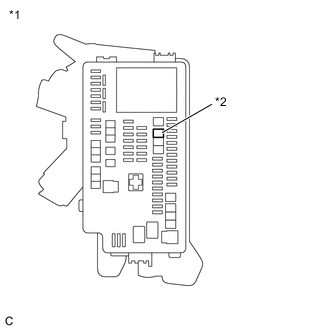
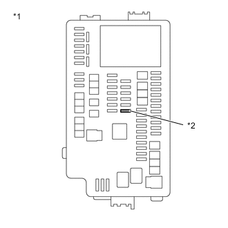
*1 No. 1 Engine Room Relay Block and No. 1 Junction Block Assembly *2 IGCT-IG Fuse Remove the IGCT-IG fuse from the No. 1 engine room relay block and No. 1 junction block assembly.
-
Measure the resistance according to the value(s) in the table below.
Standard Resistance Tester Connection Condition Specified Condition IGCT-IG fuse Power switch off Below 1 Ω -
Install the IGCT-IG fuse to the No. 1 engine room relay block and No. 1 junction block assembly.
Result Proceed to OK NG
NG
REPAIR OR REPLACE MALFUNCTIONING PARTS Click here
OK
-
-
CHECK DTC OUTPUT
-
Connect the GTS to the DLC3.
-
Turn the power switch on (IG).
-
Enter the following menus: Powertrain / Hybrid Control and Motor Generator / Trouble Codes.
-
Check for DTCs.
Powertrain > Hybrid Control > Trouble Codes
Powertrain > Motor Generator > Trouble CodesResult Result Proceed to P1CB7A2 only is output, or DTCs except the ones in the table below are also output. A DTCs of hybrid control system in the table below are output. B DTCs of motor generator control system in the table below are output. C Malfunction Content System Relevant DTC Microcomputer malfunction Motor generator control system P0A1B1F Generator Control Module Circuit Intermittent P1C2B1C Drive Motor "A" Control Module A/D Converter Circuit Voltage Out of Range P1C2B49 Drive Motor "A" Control Module A/D Converter Circuit Internal Electronic Failure P1CB746 Generator Control Module (EEPRM Backup Power) Calibration / Parameter Memory Failure Hybrid control system P0A1B49 Drive Motor "A" Control Module Internal Electronic Failure Power source circuit malfunction Motor generator control system P06B01C Generator Control Module Position Sensor REF Power Source Circuit Voltage Out of Range P06D61C Generator Control Module Offset Power Circuit Voltage Out of Range Communication malfunction Motor generator control system P312487 Lost Communication between Drive Motor "A" and HV ECU Missing Message Hybrid control system P312387 Lost Communication with Missing Message Sensor and actuator circuit malfunction Hybrid control system P0A3F16 Drive Motor "A" Position Sensor Circuit Voltage Below Threshold Tech Tips
-
P1CB7A2 may be output as a result of the malfunction indicated by the DTCs above.
-
The chart above is listed in inspection order of priority.
-
Check DTCs that are output at the same time by following the listed order. (The main cause of the malfunction can be determined without performing unnecessary inspections.)
-
-
Turn the power switch off.
B 
GO TO DTC CHART (HYBRID CONTROL SYSTEM) Click here
C
GO TO DTC CHART (MOTOR GENERATOR CONTROL SYSTEM) Click here
A
-
-
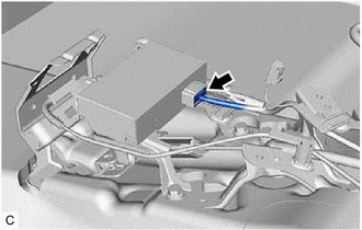
CHECK CONNECTOR CONNECTION CONDITION (INVERTER WITH CONVERTER ASSEMBLY CONNECTOR)
CAUTION:
Be sure to wear insulated gloves.
-
Check that the service plug grip is not installed.
Note
After removing the service plug grip, do not turn the power switch on (READY), unless instructed by the repair manual because this may cause a malfunction.
-
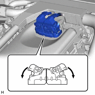
Check the connection condition of the low voltage connectors of the inverter with converter assembly and the contact pressure of each terminal. Check the terminals for deformation, and the connector for water and foreign matter.
Tech Tips
Note
Before disconnecting the connector, confirm that it is properly connected by checking that the claws of the lock levers are engaged and that the connector cannot be pulled off.
OK - The connector is connected securely. - The terminals are not deformed and are connected securely. - No water or foreign matter in the connector. Tech Tips
When connecting the connector, connect it with the lock levers raised. Rotate each lock lever downward and make sure that the connector is securely connected. When a lock lever is fully lowered, a click will be heard as its claw engages. After the click is heard, pull up on the connector to confirm that it is securely connected.
Result Result Proceed to OK A NG (The connector is not connected securely.) B NG (The terminals are not making secure contact or are deformed, or water or foreign matter exists in the connector.) C
B
CONNECT SECURELY
C
REPAIR OR REPLACE HARNESS OR CONNECTOR
A
-
-
CHECK FUSE (PCU BUB/PCU RR)
-
*1 No. 1 Engine Room Relay Block and No. 1 Junction Block Assembly *2 PCU BUB/PCU RR fuse Remove the PCU BUB/PCU RR fuse from the No. 1 engine room relay block and No. 1 junction block assembly.
-
Measure the resistance according to the value(s) in the table below.
Standard Resistance Tester Connection Condition Specified Condition PCU BUB/PCU RR fuse terminal Always Below 1 Ω -
Install the PCU BUB/PCU RR fuse.
Result Proceed to OK NG
NG
CHECK CONNECTOR CONNECTION CONDITION (INVERTER BATTERY CONNECTOR) Click here
OK
-
-
READ VALUE USING GTS (DATA LIST)
-
Connect the GTS to the DLC3.
-
Turn the power switch on (IG).
-
Enter the following menus: Powertrain / Motor Generator / Data List / Battery Voltage, IGCT Voltage.
Powertrain > Motor Generator > Data ListTester Display Battery Voltage IGCT Voltage -
Read the Data List.
Result Result Proceed to Difference between the value of "Battery Voltage" and 4 times the value of "IGCT Voltage" is less than 3 V. A Difference between the value of "Battery Voltage" and 4 times the value of "IGCT Voltage" is 3 V or more. B -
Turn the power switch off.
B
REFER TO REPLACE INVERTER WITH CONVERTER ASSEMBLY PARTS Click here
A
-
-
INSPECT RELAY (IGCT)
-
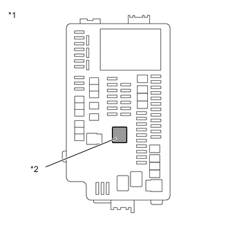
*1 No. 1 Engine Room Relay Block and No. 1 Junction Block Assembly *2 IGCT Relay Remove the IGCT relay from the No. 1 engine room relay block and No. 1 junction block assembly.
-
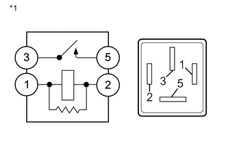
*1 IGCT Relay Measure the resistance according to the value(s) in the table below.
Standard Resistance Tester Connection Condition Specified Condition 3 - 5 Auxiliary battery voltage is not applied between terminals 1 and 2 10 kΩ or higher 3 - 5 Auxiliary battery voltage is applied between terminals 1 and 2 Below 1 Ω -
Install the IGCT relay.
Result Proceed to OK NG
NG
REPLACE RELAY (IGCT)
OK
-
-
CHECK CONNECTOR CONNECTION CONDITION (INVERTER BATTERY CONNECTOR)
-
Check the connection condition of the inverter battery connector and the contact pressure of each terminal. Check the terminals for deformation, and check the connector for water ingress and foreign matter.
Tech Tips
OK - The connector is connected securely. - The terminals are not deformed and are connected securely. - No water or foreign matter in the connector. Result Result Proceed to OK A NG (The connector is not connected securely.) B NG (The terminals are not making secure contact or are deformed, or water or foreign matter exists in the connector.) C
B
CONNECT SECURELY
C
REPAIR OR REPLACE HARNESS OR CONNECTOR
A
-
-
CHECK HARNESS AND CONNECTOR (INVERTER BATTERY - INVERTER WITH CONVERTER ASSEMBLY)
CAUTION:
Be sure to wear insulated gloves.
-
Check that the service plug grip is not installed.
Note
After removing the service plug grip, do not turn the power switch on (READY), unless instructed by the repair manual because this may cause a malfunction.
-
Disconnect the C33 inverter with converter assembly connector.
-
Disconnect the M64 inverter battery connector.
-
Connect the cable to the negative (-) auxiliary battery terminal.
-
Turn the power switch on (IG).
-
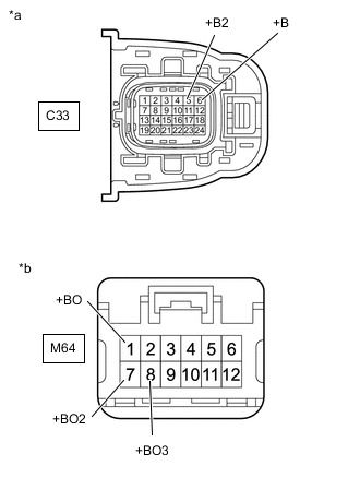
*a Front view of wire harness connector
(to Inverter with Converter Assembly)
*b Front view of wire harness connector
(to Inverter Battery)
Measure the voltage according to the value(s) in the table below.
Standard Voltage Tester Connection Condition Specified Condition M64-1 (+BO) - C33-6 (+B) Power switch on (IG) Below 1 V M64-1 (+BO) - C33-5 (+B2) Power switch on (IG) Below 1 V M64-7 (+BO2) - C33-6 (+B) Power switch on (IG) Below 1 V M64-7 (+BO2) - C33-5 (+B2) Power switch on (IG) Below 1 V M64-8 (+BO3) - C33-6 (+B) Power switch on (IG) Below 1 V M64-8 (+BO3) - C33-5 (+B2) Power switch on (IG) Below 1 V Note
Turning the power switch on (IG) with the inverter with converter assembly connector and ECM connectors disconnected causes other DTCs to be stored. Clear the DTCs after performing this inspection.
-
Turn the power switch off.
-
Measure the resistance according to the value(s) in the table below.
Standard Resistance (Check of short) Tester Connection Condition Specified Condition M64-1 (+BO) - C33-6 (+B) Power switch off Below 1 Ω M64-1 (+BO) - C33-5 (+B2) Power switch off Below 1 Ω M64-7 (+BO2) - C33-6 (+B) Power switch off Below 1 Ω M64-7 (+BO2) - C33-5 (+B2) Power switch off Below 1 Ω M64-8 (+BO3) - C33-6 (+B) Power switch off Below 1 Ω M64-8 (+BO3) - C33-5 (+B2) Power switch off Below 1 Ω Standard Resistance (Check for Short) Tester Connection Condition Specified Condition M64-1 (+BO) or C33-6 (+B) - Body ground and other terminals Power switch off 10 kΩ or higher M64-1 (+BO) or C33-5 (+B2) - Body ground and other terminals Power switch off 10 kΩ or higher M64-7 (+BO2) or C33-6 (+B) - Body ground and other terminals Power switch off 10 kΩ or higher M64-7 (+BO2) or C33-5 (+B2) - Body ground and other terminals Power switch off 10 kΩ or higher M64-8 (+BO3) or C33-6 (+B) - Body ground and other terminals Power switch off 10 kΩ or higher M64-8 (+BO3) or C33-5 (+B2) - Body ground and other terminals Power switch off 10 kΩ or higher -
Disconnect the cable from the negative (-) auxiliary battery terminal.
-
Reconnect the M64 inverter battery connector.
-
Reconnect the C33 inverter with converter assembly connector.
Result Result Proceed to OK (When result of each previous step was "OK".) A OK (When result of step 1, 2, 3 or 4 was "NG", but result of each step from 5 was "OK".) B NG C
A
REPLACE INVERTER BATTERY Click here
B
END
C
REPAIR OR REPLACE HARNESS OR CONNECTOR
-
-
CONNECT SECURELY
Result Proceed to NEXT
NEXT
GO TO STEP 5 Click here
-
CONNECT SECURELY
Result Proceed to NEXT
NEXT
GO TO STEP 5 Click here
-
REPAIR OR REPLACE MALFUNCTIONING PARTS
Result Proceed to NEXT
NEXT
GO TO STEP 5 Click here
-
REPAIR OR REPLACE MALFUNCTIONING PARTS
Result Proceed to NEXT
NEXT
GO TO STEP 5 Click here
-
CHECK CONNECTOR CONNECTION CONDITION (INVERTER BATTERY CONNECTOR)
-
Check the connection condition of the inverter battery connector and the contact pressure of each terminal. Check the terminals for deformation, and check the connector for water ingress and foreign matter.
Tech Tips
OK - The connector is connected securely. - The terminals are not deformed and are connected securely. - No water or foreign matter in the connector. Result Result Proceed to OK A NG (The connector is not connected securely.) B NG (The terminals are not making secure contact or are deformed, or water or foreign matter exists in the connector.) C
B
CONNECT SECURELY Click here
C
REPAIR OR REPLACE HARNESS OR CONNECTOR Click here
A
-
-
CHECK HARNESS AND CONNECTOR (INVERTER BATTERY - PCU BUB/PCU RR FUSE)
-
Remove the PCU BUB/ PCU RR fuse from the No. 1 engine room relay block and engine room junction block.
-
Disconnect the M64 inverter battery connector.
-
Connect the cable to the negative (-) auxiliary battery terminal.
-
Turn the power switch on (IG).
-
Measure the voltage according to the value(s) in the table below.
Standard Voltage Tester Connection Condition Specified Condition M64-10 (BUBI) - Body ground Power switch on (IG) Below 1 V Note
Turning the power switch on (IG) with the inverter with converter assembly connector and ECM connectors disconnected causes other DTCs to be stored. Clear the DTCs after performing this inspection.
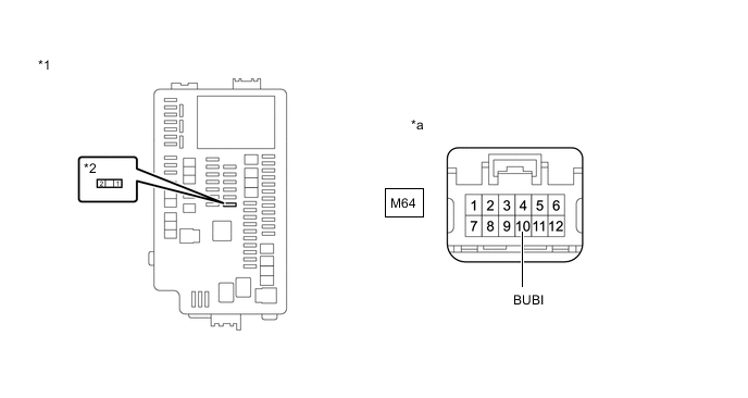
*1 No. 1 Engine Room Relay Block and No. 1 Engine room Junction Block Assembly *2 PCU BUB/PCU RR Fuse *a Front view of wire harness connector
(to Inverter Battery)
- - -
Turn the power switch off.
-
Measure the resistance according to the value(s) in the table below.
Standard Resistance (Check of short) Tester Connection Condition Specified Condition M64-10 (BUBI) - PCU BUB/PCU RR fuse Power switch off Below 1 Ω Standard Resistance (Check for Short) Tester Connection Condition Specified Condition M64-10 (BUBI) or PCU BUB/PCU RR fuse - Body ground and other terminals Power switch off 10 kΩ or higher -
Disconnect the cable from the negative (-) auxiliary battery terminal.
-
Reconnect the M64 inverter battery connector.
-
Reinstall the PCU BUB/PCU RR fuse.
Result Proceed to OK NG
NG
REPAIR OR REPLACE HARNESS OR CONNECTOR Click here
OK
-
-
REPLACE INVERTER BATTERY
Tech Tips
Result Proceed to NEXT
NEXT
REPLACE FUSE (PCU BUB/PCU RR)
-
CONNECT SECURELY
Result Proceed to NEXT
NEXT
REPLACE FUSE (PCU BUB/PCU RR)
-
REPAIR OR REPLACE HARNESS OR CONNECTOR
Result Proceed to NEXT
NEXT
REPLACE FUSE (PCU BUB/PCU RR)
-
REPAIR OR REPLACE HARNESS OR CONNECTOR
Result Proceed to NEXT
NEXT
REPLACE FUSE (PCU BUB/PCU RR)