HYBRID CONTROL SYSTEM, Diagnostic DTC:P0AFC62, P0B3B14, P0B4014, P0B4514, P0B4A14, P0B4F14, P0B5414, P0B5914, P0B5E14, P0B6314, P0B6814, P308A13
| DTC Code | DTC Name |
|---|---|
| P0AFC62 | Hybrid/EV Battery Sensor Module Signal Compare Failure |
| P0B3B14 | Hybrid/EV Battery Voltage Sensor "A" Circuit Short to Ground or Open |
| P0B4014 | Hybrid/EV Battery Voltage Sensor "B" Circuit Short to Ground or Open |
| P0B4514 | Hybrid/EV Battery Voltage Sensor "C" Circuit Short to Ground or Open |
| P0B4A14 | Hybrid/EV Battery Voltage Sensor "D" Circuit Short to Ground or Open |
| P0B4F14 | Hybrid/EV Battery Voltage Sensor "E" Circuit Short to Ground or Open |
| P0B5414 | Hybrid/EV Battery Voltage Sensor "F" Circuit Short to Ground or Open |
| P0B5914 | Hybrid/EV Battery Voltage Sensor "G" Circuit Short to Ground or Open |
| P0B5E14 | Hybrid/EV Battery Voltage Sensor "H" Circuit Short to Ground or Open |
| P0B6314 | Hybrid/EV Battery Voltage Sensor "I" Circuit Short to Ground or Open |
| P0B6814 | Hybrid/EV Battery Voltage Sensor "J" Circuit Short to Ground or Open |
| P308A13 | Hybrid/EV Battery Voltage Sensor All Circuit Open |
DESCRIPTION
Refer to the description for DTC P1AC000.
| DTC No. | Detection Item | DTC Detection Condition | Trouble Area | MIL | Warning Indicate |
|---|---|---|---|---|---|
| P0AFC62 | Hybrid/EV Battery Sensor Module Signal Compare Failure | The difference between the voltage output by detection circuit C and the total of the voltage output by detection circuits A and B exceeds a threshold. HINT: The battery voltage sensor uses 3 voltage detection circuits (A, B and C) to detect the voltage of the battery blocks. (1 trip detection logic) |
|
Comes on | Master Warning Light: Comes on |
| P0B3B14 | Hybrid/EV Battery Voltage Sensor "A" Circuit Short to Ground or Open | The battery block voltage detection line has a malfunction and any of the battery block voltages become lower than the specified value (open). (1 trip detection logic) |
|
Comes on | Master Warning Light: Comes on |
| P0B4014 | Hybrid/EV Battery Voltage Sensor "B" Circuit Short to Ground or Open | The battery block voltage detection line has a malfunction and any of the battery block voltages become lower than the specified value (open). (1 trip detection logic) |
|
Comes on | Master Warning Light: Comes on |
| P0B4514 | Hybrid/EV Battery Voltage Sensor "C" Circuit Short to Ground or Open | The battery block voltage detection line has a malfunction and any of the battery block voltages become lower than the specified value (open). (1 trip detection logic) |
|
Comes on | Master Warning Light: Comes on |
| P0B4A14 | Hybrid/EV Battery Voltage Sensor "D" Circuit Short to Ground or Open | The battery block voltage detection line has a malfunction and any of the battery block voltages become lower than the specified value (open). (1 trip detection logic) |
|
Comes on | Master Warning Light: Comes on |
| P0B4F14 | Hybrid/EV Battery Voltage Sensor "E" Circuit Short to Ground or Open | The battery block voltage detection line has a malfunction and any of the battery block voltages become lower than the specified value (open). (1 trip detection logic) |
|
Comes on | Master Warning Light: Comes on |
| P0B5414 | Hybrid/EV Battery Voltage Sensor "F" Circuit Short to Ground or Open | The battery block voltage detection line has a malfunction and any of the battery block voltages become lower than the specified value (open). (1 trip detection logic) |
|
Comes on | Master Warning Light: Comes on |
| P0B5914 | Hybrid/EV Battery Voltage Sensor "G" Circuit Short to Ground or Open | The battery block voltage detection line has a malfunction and any of the battery block voltages become lower than the specified value (open). (1 trip detection logic) |
|
Comes on | Master Warning Light: Comes on |
| P0B5E14 | Hybrid/EV Battery Voltage Sensor "H" Circuit Short to Ground or Open | The battery block voltage detection line has a malfunction and any of the battery block voltages become lower than the specified value (open). (1 trip detection logic) |
|
Comes on | Master Warning Light: Comes on |
| P0B6314 | Hybrid/EV Battery Voltage Sensor "I" Circuit Short to Ground or Open | The battery block voltage detection line has a malfunction and any of the battery block voltages become lower than the specified value (open). (1 trip detection logic) |
|
Comes on | Master Warning Light: Comes on |
| P0B6814 | Hybrid/EV Battery Voltage Sensor "J" Circuit Short to Ground or Open | The battery block voltage detection line has a malfunction and any of the battery block voltages become lower than the specified value (open). (1 trip detection logic) |
|
Comes on | Master Warning Light: Comes on |
| P308A13 | Hybrid/EV Battery Voltage Sensor All Circuit Open | The battery block voltage detection line is open (all blocks) or all battery block voltages become lower than the specified value (possibility of open or loosely connected connector). (1 trip detection logic) |
|
Comes on | Master Warning Light: Comes on |
Tech Tips
Hybrid Battery Block 1 to 9 Voltage values smaller than 2.0 V may not be shown in the Data List because a fail-safe value is substituted.
| DTC No. | Data List |
|---|---|
| P0AFC62 | Hybrid Battery Block 1 to 9 Voltage *1 |
| P0B3B14 | |
| P0B4014 | |
| P0B4514 | |
| P0B4A14 | |
| P0B4F14 | |
| P0B5414 | |
| P0B5914 | |
| P0B5E14 | |
| P0B6314 | |
| P0B6814 | |
| P308A13 |
|
Tech Tips
-
*1: Under normal conditions, the values of Hybrid Battery Block 1, 2, 8 and 9 Voltage will be approximately 16 V and Hybrid Battery Block 3, 4, 5, 6 and 7 Voltage will be approximately 32 V.
-
If there is a short or open in a battery block voltage detection line, the value of Hybrid Battery Block Voltage for the corresponding battery block will be lower than 8 V.
CONFIRMATION DRIVING PATTERN
Tech Tips
After repair has been completed, clear the DTC and then check that the vehicle has returned to normal by performing the following All Readiness check procedure.
-
Connect the GTS to the DLC3.
-
Turn the power switch on (IG) and turn the GTS on.
-
Clear the DTCs (even if no DTCs are stored, perform the clear DTC procedure).
-
Turn the power switch off and wait for 2 minutes or more.
-
Turn the power switch on (IG) and turn the GTS on.
-
With power switch on (IG) and wait for 20 seconds or more.
-
Enter the following menus: Powertrain / Hybrid Control / Utility / All Readiness.
-
Check the DTC judgment result.
Tech Tips
-
If the judgment result shows NORMAL, the system is normal.
-
If the judgment result shows ABNORMAL, the system has a malfunction.
-
If the judgment result shows INCOMPLETE or N/A, perform driving pattern again.
-
CAUTION / NOTICE / HINT
CAUTION:
-
Before inspecting the high-voltage system, take safety precautions to prevent electrical shocks, such as wearing insulated gloves and removing the service plug grip. After removing the service plug grip, put it in your pocket to prevent other technicians from accidentally reconnecting it while you are working on the high-voltage system.
-
After removing the service plug grip, wait for at least 10 minutes before touching any of the high-voltage connectors or terminals. After waiting for 10 minutes, check the voltage at the terminals in the inspection point in the inverter with converter assembly. The voltage should be 0 V before beginning work.
Tech Tips
Waiting for at least 10 minutes is required to discharge the high-voltage capacitor inside the inverter with converter assembly.
-
When disposing of an HV battery, make sure to return it through an authorized collection agent who is capable of handling it safely. If the HV battery is returned via the manufacturer specified route, it will be returned properly and in a safe manner by an authorized collection agent.
Note
After turning the power switch off, waiting time may be required before disconnecting the cable from the negative (-) auxiliary battery terminal. Therefore, make sure to read the disconnecting the cable from the negative (-) auxiliary battery terminal notices before proceeding with work.
PROCEDURE
-
CHECK DTC OUTPUT (HYBRID CONTROL)
-
Connect the GTS to the DLC3.
-
Turn the power switch on (IG).
-
Enter the following menus: Powertrain / Hybrid Control / Trouble Codes.
-
Check and record any HV system DTCs and freeze frame data.
Powertrain > Hybrid Control > Trouble Codes -
Read output DTCs.
Result Result Proceed to P0AFC00, P0AFC96 or P308A12 is output A Other than above B -
Turn the power switch off.
A 
GO TO DTC CHART (HYBRID CONTROL SYSTEM) Click here
B 
-
-
CHECK CONNECTOR CONNECTION CONDITION
CAUTION:
Be sure to wear insulated gloves.
-
Check that the service plug grip is not installed.
Note
After removing the service plug grip, do not turn the power switch on (READY), unless instructed by the repair manual because this may cause a malfunction.
-
Remove the No. 1 hybrid battery exhaust duct.
Tech Tips
-
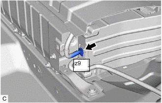
Check the connections of the z9 battery voltage sensor connector.
Tech Tips
OK The connector is connected securely and there are no contact problems. Result Result OK NG -
Install the No. 1 hybrid battery exhaust duct.
NG
CONNECT SECURELY
OK
-
-
REPLACE BATTERY VOLTAGE SENSOR
Tech Tips
Result Proceed to NEXT
NEXT
-
CLEAR DTC (HYBRID CONTROL)
-
Connect the GTS to the DLC3.
-
Turn the power switch on (IG).
-
Clear the DTCs.
Powertrain > Hybrid Control > Clear DTCs -
Turn the power switch off.
-
Turn the power switch on (IG) and wait for 10 seconds or more.
Result Proceed to NEXT
NEXT
-
-
RECONFIRM DTC OUTPUT (HYBRID CONTROL)
-
Connect the GTS to the DLC3.
-
Turn the power switch on (IG).
-
Enter the following menus: Powertrain / Hybrid Control / Trouble Codes.
-
Read output DTCs.
Powertrain > Hybrid Control > Trouble CodesResult Result Proceed to P0AFC62, P0B3B14, P0B4014, P0B4514, P0B4A14, P0B4F14, P0B5414, P0B5914, P0B5E14, P0B6314, P0B6814 and P308A13 are not output A P0AFC62, P0B3B14, P0B4014, P0B4514, P0B4A14, P0B4F14, P0B5414, P0B5914, P0B5E14, P0B6314, P0B6814 or P308A13 is output B -
Turn the power switch off.
A
END
B
REPLACE HV BATTERY Click here
-