HYBRID CONTROL SYSTEM, Diagnostic DTC:P0A9B1C, P0AC51C, P0ACA1C
| DTC Code | DTC Name |
|---|---|
| P0A9B1C | Hybrid/EV Battery Temperature Sensor "A" Voltage Out of Range |
| P0AC51C | Hybrid/EV Battery Temperature Sensor "B" Voltage Out of Range |
| P0ACA1C | Hybrid/EV Battery Temperature Sensor "C" Voltage Out of Range |
DESCRIPTION
These DTCs will be stored if the difference between the maximum and minimum output of each battery temperature sensors exceeds a certain amount and if the output of one battery temperature sensor deviates from that of the other sensors.
| DTC No. | Detection Item | DTC Detection Condition | Trouble Area | MIL | Warning Indicate |
|---|---|---|---|---|---|
| P0A9B1C | Hybrid/EV Battery Temperature Sensor "A" Voltage Out of Range | The performance of battery temperature sensor 0 is abnormal; the difference in output between it and other battery temperature sensors is excessively large. (1 trip detection logic) |
|
Comes on | Master Warning Light: Comes on |
| P0AC51C | Hybrid/EV Battery Temperature Sensor "B" Voltage Out of Range | The performance of battery temperature sensor 1 is abnormal; the difference in output between it and other battery temperature sensors is excessively large. (1 trip detection logic) |
|
Comes on | Master Warning Light: Comes on |
| P0ACA1C | Hybrid/EV Battery Temperature Sensor "C" Voltage Out of Range | The performance of battery temperature sensor 2 is abnormal; the difference in output between it and other battery temperature sensors is excessively large. (1 trip detection logic) |
|
Comes on | Master Warning Light: Comes on |
| DTC No. | Data List |
|---|---|
| P0A9B1C |
|
| P0AC51C | |
| P0ACA1C |
Tech Tips
If the vehicle as is left as is for 24 hours, the value of "Hybrid Battery Temperature" will be almost the same as the ambient temperature.
The following items can be helpful when performing repairs:
-
Vehicle Speed
-
Ambient Temperature
Data List
CONFIRMATION DRIVING PATTERN
Tech Tips
After repair has been completed, clear the DTC and then check that the vehicle has returned to normal by performing the following All Readiness check procedure.
-
Connect the GTS to the DLC3.
-
Turn the power switch on (IG) and turn the GTS on.
-
Clear the DTCs (even if no DTCs are stored, perform the clear DTC procedure).
-
Turn the power switch off and wait for 2 minutes or more.
-
Turn the power switch on (IG) and turn the GTS on.
-
With power switch on (IG) and wait for 10 seconds or more.
-
Enter the following menus: Powertrain / Hybrid Control / Utility / All Readiness.
-
Check the DTC judgment result.
Tech Tips
-
If the judgment result shows NORMAL, the system is normal.
-
If the judgment result shows ABNORMAL, the system has a malfunction.
-
If the judgment result shows INCOMPLETE or N/A, perform driving pattern again.
-
PROCEDURE
-
CHECK DTC OUTPUT (HYBRID CONTROL)
-
Connect the GTS to the DLC3.
-
Turn the power switch on (IG).
-
Enter the following menus: Powertrain / Hybrid Control / Trouble Codes.
-
Check for DTCs.
Powertrain > Hybrid Control > Trouble CodesResult Result Proceed to P0AFC00 or P0AFC96 is output A Other than above B -
Turn the power switch off.
A 
GO TO DTC CHART (HYBRID CONTROL SYSTEM) Click here
B 
-
-
CHECK INSTALLATION OF TEMPERATURE SENSOR (HYBRID BATTERY TEMPERATURE)
CAUTION:
Be sure to wear insulated gloves and protective goggles.
-
Check that the service plug grip is not installed.
Note
After removing the service plug grip, do not turn the power switch on (READY), unless instructed by the repair manual because this may cause a malfunction.
-
Remove the upper No. 1 hybrid battery cover sub-assembly.
Tech Tips
-
Visually check the installation condition of the relevant battery temperature sensor.
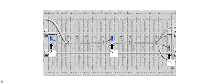
*1 Battery Temperature Sensor 0 *2 Battery Temperature Sensor 1 *3 Battery Temperature Sensor 2 - - Standard Condition Each battery temperature sensor is installed in the correct location with the correct orientation and its claws are engaged securely. Result Result Proceed to Each battery temperature sensor is installed in the correct location with the correct orientation and its claws are engaged securely. A Claws are damaged. B Any of battery temperature sensors are not installed correctly, but claws are not damaged. C -
Install the upper No. 1 hybrid battery cover sub-assembly.
B
REPLACE HYBRID BATTERY THERMISTOR Click here
C
INSTALL PARTS CORRECTLY
A
-
-
CHECK HV BATTERY (BATTERY TEMPERATURE SENSOR)
CAUTION:
Be sure to wear insulated gloves.
-
Check that the service plug grip is not installed.
Note
After removing the service plug grip, do not turn the power switch on (READY), unless instructed by the repair manual because this may cause a malfunction.
-
Remove the No. 1 hybrid battery exhaust duct.
Tech Tips
-
Disconnect the z9 battery voltage sensor connector.
Note
Before disconnecting the connector, check that it is not loose or disconnected.
-
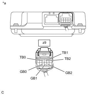
*a Rear view of wire harness connector
(to Battery Voltage Sensor)
Measure the resistance of the circuit for the malfunctioning sensor (battery temperature sensor 0 to 2).
Tester Connection Tester Connection Battery Temperature Sensor z9-4 (TB0) - z9-10 (GB0) 0 z9-3 (TB1) - z9-9 (GB1) 1 z9-2 (TB2) - z9-8 (GB2) 2 Standard Resistance Thermistor Temperature Condition Specified Condition 0°C (32°F) Power switch off 26.7 to 27.8 kΩ 25°C (77°F) Power switch off 9.9 to 10.1 kΩ 40°C (104°F) Power switch off 5.73 to 5.92 kΩ Note
When taking a measurement with a tester, do not apply excessive force to the tester probe to avoid damaging the holder.
-
Reconnect the z9 battery voltage sensor connector.
-
Install the No. 1 hybrid battery exhaust duct.
Result Proceed to OK NG
NG 
GO TO STEP 5 Click here
OK
-
-
CHECK HV BATTERY (BATTERY TEMPERATURE SENSOR)
CAUTION:
Be sure to wear insulated gloves.
-
Check that the service plug grip is not installed.
Note
After removing the service plug grip, do not turn the power switch on (READY), unless instructed by the repair manual because this may cause a malfunction.
-
Remove the No. 1 hybrid battery exhaust duct.
Tech Tips
-
Disconnect the M35 and z9 battery voltage sensor connectors.
Note
Before disconnecting the connector, check that it is not loose or disconnected.
-
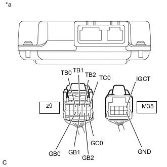
*a Rear view of wire harness connector
(to Battery Voltage Sensor)
Measure the resistance according to the value(s) in the table below.
Standard Resistance Tester Connection Condition Specified Condition z9-4 (TB0) - M35-1 (IGCT) Power switch off 10 kΩ or higher z9-4 (TB0) - M35-5 (GND) Power switch off 10 kΩ or higher z9-10 (GB0) - M35-1 (IGCT) Power switch off 10 kΩ or higher z9-10 (GB0) - M35-5 (GND) Power switch off 10 kΩ or higher z9-3 (TB1) - M35-1 (IGCT) Power switch off 10 kΩ or higher z9-3 (TB1) - M35-5 (GND) Power switch off 10 kΩ or higher z9-9 (GB1) - M35-1 (IGCT) Power switch off 10 kΩ or higher z9-9 (GB1) - M35-5 (GND) Power switch off 10 kΩ or higher z9-2 (TB2) - M35-1 (IGCT) Power switch off 10 kΩ or higher z9-2 (TB2) - M35-5 (GND) Power switch off 10 kΩ or higher z9-8 (GB2) - M35-1 (IGCT) Power switch off 10 kΩ or higher z9-8 (GB2) - M35-5 (GND) Power switch off 10 kΩ or higher z9-1 (TC0) - M35-1 (IGCT) Power switch off 10 kΩ or higher z9-1 (TC0) - M35-5 (GND) Power switch off 10 kΩ or higher z9-7 (GC0) - M35-1 (IGCT) Power switch off 10 kΩ or higher z9-7 (GC0) - M35-5 (GND) Power switch off 10 kΩ or higher Note
When taking a measurement with a tester, do not apply excessive force to the tester probe to avoid damaging the holder.
-
Reconnect the M35 and z9 battery voltage sensor connectors.
-
Install the No. 1 hybrid battery exhaust duct.
Result Proceed to OK NG
OK
REPLACE BATTERY VOLTAGE SENSOR Click here
NG
-
-
CHECK HARNESS AND CONNECTOR (BATTERY TEMPERATURE SENSOR)
CAUTION:
Be sure to wear insulated gloves and protective goggles.
-
Check that the service plug grip is not installed.
Note
After removing the service plug grip, do not turn the power switch on (READY), unless instructed by the repair manual because this may cause a malfunction.
-
Remove the upper No. 1 hybrid battery cover sub-assembly.
Tech Tips
-
Check the wire harness and connectors of the battery temperature sensor for abnormalities by sight and touch.
Specified Condition There are no open or short circuits in the wire harness and connectors. There are no short circuits to other wire harnesses. Result Proceed to OK NG -
Install the upper hybrid battery cover sub-assembly.
OK
REPLACE HYBRID BATTERY THERMISTOR Click here
NG
REPAIR HARNESS OR CONNECTOR (BATTERY TEMPERATURE SENSOR)
-