HYBRID CONTROL SYSTEM, Diagnostic DTC:P0ABF11, P0ABF15, P1CBB12, P1CBB14
| DTC Code | DTC Name |
|---|---|
| P0ABF11 | Hybrid/EV Battery Current Sensor "A" Circuit Short to Ground |
| P0ABF15 | Hybrid/EV Battery Current Sensor "A" Circuit Short to Auxiliary Battery or Open |
| P1CBB12 | Hybrid/EV Battery Current Sensor Power Supply Circuit Short to Auxiliary Battery |
| P1CBB14 | Hybrid/EV Battery Current Sensor Power Supply Circuit Short to Ground or Open |
DESCRIPTION
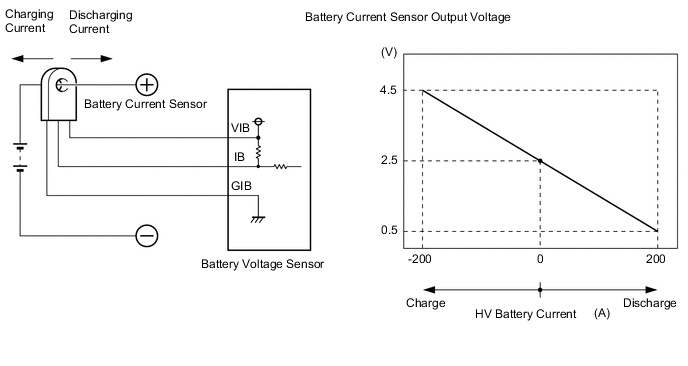
A battery current sensor is installed to the positive (+) terminal side of the HV battery and detects current flowing from the HV battery. The battery current sensor outputs voltage, which changes between 0 and 5 V according to the detected amperage, to the IB terminal of the battery voltage sensor. The battery voltage sensor sends signals to the hybrid vehicle control ECU. The hybrid vehicle control ECU determines the charging and discharging amount of the HV battery based on the received signals and calculates the SOC of the HV battery through the accumulated amperage.
| DTC No. | Detection Item | DTC Detection Condition | Trouble Area | MIL | Warning Indicate |
|---|---|---|---|---|---|
| P0ABF11 | Hybrid/EV Battery Current Sensor "A" Circuit Short to Ground | The battery current sensor output voltage is excessively low. (1 trip detection logic) |
|
Comes on | Master Warning Light: Comes on |
| P0ABF15 | Hybrid/EV Battery Current Sensor "A" Circuit Short to Auxiliary Battery or Open | The battery current sensor output voltage is excessively high. (1 trip detection logic) |
|
Comes on | Master Warning Light: Comes on |
| P1CBB12 | Hybrid/EV Battery Current Sensor Power Supply Circuit Short to Auxiliary Battery | Power source voltage of the battery current sensor is excessively high. (1 trip detection logic) |
|
Comes on | Master Warning Light: Comes on |
| P1CBB14 | Hybrid/EV Battery Current Sensor Power Supply Circuit Short to Ground or Open | Power source voltage of the battery current sensor is excessively low. (1 trip detection logic) |
|
Comes on | Master Warning Light: Comes on |
| DTC No. | Data List |
|---|---|
| P0ABF11 | Hybrid Battery Current *1 |
| P0ABF15 | |
| P1CBB12 | |
| P1CBB14 |
Tech Tips
*1: The value of "Hybrid Battery Current *1" will be approximately 0 A when the power switch is on (IG) (READY off).
CONFIRMATION DRIVING PATTERN
Tech Tips
After repair has been completed, clear the DTC and then check that the vehicle has returned to normal by performing the following All Readiness check procedure.
-
Connect the GTS to the DLC3.
-
Turn the power switch on (IG) and turn the GTS on.
-
Clear the DTCs (even if no DTCs are stored, perform the clear DTC procedure).
-
Turn the power switch off and wait for 2 minutes or more.
-
Turn the power switch on (IG) and turn the GTS on.
-
With power switch on (IG) and wait for 10 seconds or more.
-
Enter the following menus: Powertrain / Hybrid Control / Utility / All Readiness.
-
Check the DTC judgment result.
Tech Tips
-
If the judgment result shows NORMAL, the system is normal.
-
If the judgment result shows ABNORMAL, the system has a malfunction.
-
If the judgment result shows INCOMPLETE or N/A, perform driving pattern again.
-
WIRING DIAGRAM
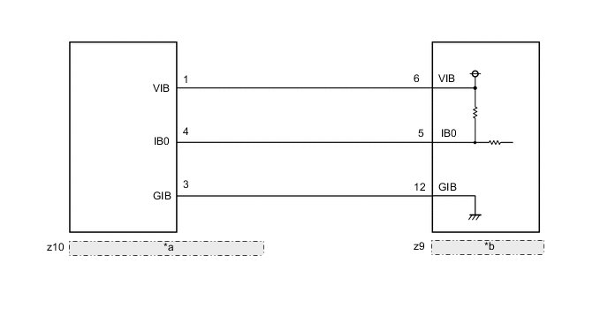
| *a | HV Battery Junction Block Assembly (Battery Current Sensor) |
| *b | Battery Voltage Sensor |
Refer to the wiring diagram for DTC P0AFC00.
CAUTION / NOTICE / HINT
CAUTION:
-
Before inspecting the high-voltage system, take safety precautions to prevent electrical shocks, such as wearing insulated gloves and removing the service plug grip. After removing the service plug grip, put it in your pocket to prevent other technicians from accidentally reconnecting it while you are working on the high-voltage system.
-
After removing the service plug grip, wait for at least 10 minutes before touching any of the high-voltage connectors or terminals. After waiting for 10 minutes, check the voltage at the terminals in the inspection point in the inverter with converter assembly. The voltage should be 0 V before beginning work.
Tech Tips
Waiting for at least 10 minutes is required to discharge the high-voltage capacitor inside the inverter with converter assembly.
Note
After turning the power switch off, waiting time may be required before disconnecting the cable from the negative (-) auxiliary battery terminal. Therefore, make sure to read the disconnecting the cable from the negative (-) auxiliary battery terminal notices before proceeding with work.
PROCEDURE
-
CHECK DTC OUTPUT (HYBRID CONTROL)
-
Connect the GTS to the DLC3.
-
Turn the power switch on (IG).
-
Enter the following menus: Powertrain / Hybrid Control / Trouble Codes.
Powertrain > Hybrid Control > Trouble Codes -
Check for DTCs.
Result Result Proceed to P0AFC00, P0AFC96 or P308A12 is output A Other than above B -
Turn the power switch off.
A 
GO TO DTC CHART (HYBRID CONTROL SYSTEM) Click here
B 
-
-
CHECK BATTERY VOLTAGE SENSOR (IGCT VOLTAGE)
CAUTION:
Be sure to wear insulated gloves.
-
Check that the service plug grip is not installed.
Note
After removing the service plug grip, do not turn the power switch on (READY), unless instructed by the repair manual because this may cause a malfunction.
-
Remove the No. 1 hybrid battery exhaust duct.
Tech Tips
-
Connect the cable to the negative (-) auxiliary battery terminal.
-
Turn the power switch on (IG).
-
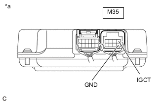
*a Component with harness connected
(Battery Voltage Sensor)
Measure the voltage according to the value(s) in the table below.
Standard Voltage Tester Connection Condition Specified Condition M35-1 (IGCT) - M35-5 (GND) Power switch on (IG) 11 to 14 V Note
Turning the power switch on (IG) with the service plug grip removed causes other DTCs to be stored. Clear the DTCs after performing this inspection.
Tech Tips
As there might be an intermittent malfunction in the battery voltage sensor power source circuit, inspect the following even if the measured voltage is as specified:
-
Installation condition of fuse(s) (before removing fuse(s)) (IGCT circuit)
-
Fuse condition (before and after removing fuse(s)) (IGCT circuit)
-
Connection condition of connectors (IGCT circuit)
-
Wire harness condition (IGCT circuit)
-
Wire harness condition (GND circuit)
-
-
Turn the power switch off.
-
Disconnect the cable from the negative (-) auxiliary battery terminal.
-
Install the No. 1 hybrid battery exhaust duct.
Result Proceed to OK NG
NG
REPAIR OR REPLACE HARNESS OR CONNECTOR (BATTERY VOLTAGE SENSOR POWER SOURCE CIRCUIT)
OK
-
-
CHECK HARNESS AND CONNECTOR (BATTERY VOLTAGE SENSOR - HV BATTERY JUNCTION BLOCK ASSEMBLY)
CAUTION:
Be sure to wear insulated gloves.
-
Check that the service plug grip is not installed.
Note
After removing the service plug grip, do not turn the power switch on (READY), unless instructed by the repair manual because this may cause a malfunction.
-
Remove the No. 1 HV battery cover panel RH.
Tech Tips
-
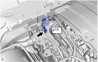
Disconnect the z10 battery current sensor connector from the HV battery junction block assembly.
Note
Before disconnecting the connector, check that it is not loose or disconnected.
-
Remove the No. 1 hybrid battery exhaust duct.
Tech Tips
-
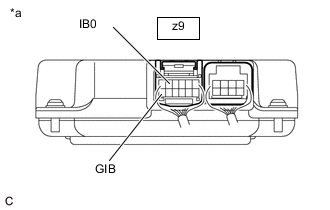
Disconnect the z9 battery voltage sensor connector.
Note
Before disconnecting the connector, check that it is not loose or disconnected.
-
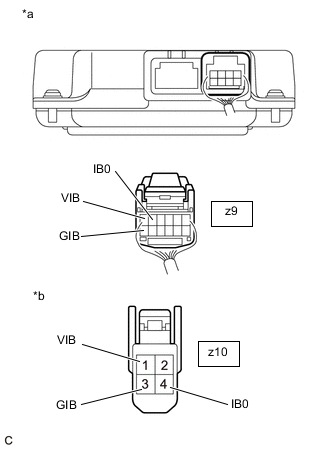
*a Rear view of wire harness connector
(to Battery Voltage Sensor)
*b Front view of wire harness connector
(to HV Battery Junction Block Assembly (Battery Current Sensor))
Measure the resistance according to the value(s) in the tables below.
Standard Resistance (Check for Open) Tester Connection Condition Specified Condition z9-5 (IB0) - z10-4 (IB0) Power switch off Below 1 Ω z9-12 (GIB) - z10-3 (GIB) Power switch off Below 1 Ω z9-6 (VIB) - z10-1 (VIB) Power switch off Below 1 Ω Standard Resistance (Check for Short) Tester Connection Condition Specified Condition z9-5 (IB0) or z10-4 (IB0) - Body ground and other terminals Power switch off 10 kΩ or higher z9-12 (GIB) or z10-3 (GIB) - Body ground and other terminals Power switch off 10 kΩ or higher z9-6 (VIB) or z10-1 (VIB) - Body ground and other terminals Power switch off 10 kΩ or higher Tech Tips
As the battery harness is not available as a supply part, if the harness cannot be repaired, replace the HV battery.
-
Reconnect the z9 battery voltage sensor connector.
-
Install the No. 1 hybrid battery exhaust duct.
-
Reconnect the z10 battery current sensor connector to the HV battery junction block assembly.
-
Install the No. 1 HV battery cover panel RH.
Result Proceed to OK NG
NG
REPAIR HARNESS OR CONNECTOR (BATTERY CURRENT SENSOR)
OK
-
-
CHECK BATTERY VOLTAGE SENSOR (VIB VOLTAGE)
CAUTION:
Be sure to wear insulated gloves.
-
Check that the service plug grip is not installed.
Note
After removing the service plug grip, do not turn the power switch on (READY), unless instructed by the repair manual because this may cause a malfunction.
-
Remove the No. 1 hybrid battery exhaust duct.
Tech Tips
-
Connect the cable to the negative (-) auxiliary battery terminal.
-
Turn the power switch on (IG).
-
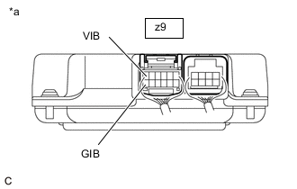
*a Component with harness connected
(Battery Voltage Sensor)
Measure the voltage according to the value(s) in the table below.
Standard Voltage Tester Connection Condition Specified Condition z9-6 (VIB) - z9-12 (GIB) Power switch on (IG) 4.6 to 5.4 V Note
Turning the power switch on (IG) with the service plug grip removed causes other DTCs to be stored. Clear the DTCs after performing this inspection.
-
Turn the power switch off.
-
Disconnect the cable from the negative (-) auxiliary battery terminal.
-
Install the No. 1 hybrid battery exhaust duct.
Result Proceed to OK NG
NG 
CHECK BATTERY VOLTAGE SENSOR (VIB VOLTAGE) Click here
OK
-
-
CHECK BATTERY VOLTAGE SENSOR (GIB - GND)
CAUTION:
Be sure to wear insulated gloves.
-
Check that the service plug grip is not installed.
Note
After removing the service plug grip, do not turn the power switch on (READY), unless instructed by the repair manual because this may cause a malfunction.
-
Remove the No. 1 hybrid battery exhaust duct.
Tech Tips
-
Disconnect the z9 and M35 battery voltage sensor connectors.
Note
Before disconnecting the connector, check that it is not loose or disconnected.
-
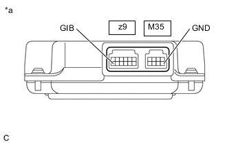
*a Component without harness connected
(Battery Voltage Sensor)
Measure the resistance according to the value(s) in the tables below.
Standard Resistance Tester Connection Condition Specified Condition z9-12 (GIB) - M35-5 (GND) Power switch off Below 1 Ω -
Reconnect the z9 and M35 battery voltage sensor connectors.
-
Install the No. 1 hybrid battery exhaust duct.
Result Proceed to OK NG
NG
REPLACE BATTERY VOLTAGE SENSOR Click here
OK
-
-
CHECK BATTERY VOLTAGE SENSOR (BATTERY CURRENT SENSOR OUTPUT VOLTAGE)
CAUTION:
Be sure to wear insulated gloves.
-
Check that the service plug grip is not installed.
Note
After removing the service plug grip, do not turn the power switch on (READY), unless instructed by the repair manual because this may cause a malfunction.
-
Remove the No. 1 hybrid battery exhaust duct.
Tech Tips
-
Connect the cable to the negative (-) auxiliary battery terminal.
-
Turn the power switch on (IG).
-

*a Component with harness connected
(Battery Voltage Sensor)
Measure the voltage according to the value(s) in the table below.
Standard Voltage Tester Connection Condition Specified Condition z9-5 (IB0) - z9-12 (GIB) Power switch on (IG) 2.46 to 2.54 V Note
Turning the power switch on (IG) with the service plug grip removed causes other DTCs to be stored. Clear the DTCs after performing this inspection.
-
Turn the power switch off.
-
Disconnect the cable from the negative (-) auxiliary battery terminal.
-
Install the No. 1 hybrid battery exhaust duct.
Result Result Proceed to OK A NG(Voltage is outside the specified value and 0.4 V or more.) B NG(Voltage is outside the specified value and less than 0.4 V.) C
A
REPLACE BATTERY VOLTAGE SENSOR Click here
C
CHECK BATTERY VOLTAGE SENSOR (BATTERY CURRENT SENSOR OUTPUT VOLTAGE) Click here
B
-
-
CHECK BATTERY VOLTAGE SENSOR (VIB - IB0)
CAUTION:
Be sure to wear insulated gloves.
-
Check that the service plug grip is not installed.
Note
After removing the service plug grip, do not turn the power switch on (READY), unless instructed by the repair manual because this may cause a malfunction.
-
Remove the No. 1 hybrid battery exhaust duct.
Tech Tips
-
Disconnect the z9 battery voltage sensor connectors.
Note
Before disconnecting the connector, check that it is not loose or disconnected.
-
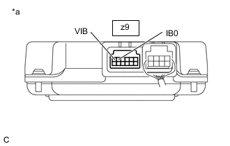
*a Component without harness connected
(Battery Voltage Sensor)
Measure the resistance according to the value(s) in the tables below.
Tester Connection Condition Specified Condition z9-6 (VIB) - z9-5 (IB0) Power switch off Below 1 Ω Result Proceed to OK NG -
Reconnect the z9 battery voltage sensor connectors.
-
Install the No. 1 hybrid battery exhaust duct.
OK
REPLACE BATTERY VOLTAGE SENSOR Click here
NG
REPLACE HV BATTERY JUNCTION BLOCK ASSEMBLY Click here
-
-
CHECK BATTERY VOLTAGE SENSOR (BATTERY CURRENT SENSOR OUTPUT VOLTAGE)
CAUTION:
Be sure to wear insulated gloves.
-
Check that the service plug grip is not installed.
Note
After removing the service plug grip, do not turn the power switch on (READY), unless instructed by the repair manual because this may cause a malfunction.
-
Remove the No. 1 HV battery cover panel RH.
Tech Tips
-
Disconnect the z10 battery current sensor connector from the HV battery junction block assembly.
Note
Before disconnecting the connector, check that it is not loose or disconnected.
-
Remove the No. 1 hybrid battery exhaust duct.
Tech Tips
-
Connect the cable to the negative (-) auxiliary battery terminal.
-
Turn the power switch on (IG).
-
*a Component with harness connected
(Battery Voltage Sensor)
Measure the voltage according to the value(s) in the table below.
Standard Voltage Tester Connection Condition Specified Condition z9-5 (IB0) - z9-12 (GIB) Power switch on (IG) 4.6 to 5.4 V Note
Turning the power switch on (IG) with the service plug grip removed causes other DTCs to be stored. Clear the DTCs after performing this inspection.
-
Turn the power switch off.
-
Disconnect the cable from the negative (-) auxiliary battery terminal.
-
Install the No. 1 hybrid battery exhaust duct.
-
Reconnect the z10 battery current sensor connector to the HV battery junction block assembly.
-
Install the No. 1 HV battery cover panel RH.
Result Proceed to OK NG
OK
REPLACE HV BATTERY JUNCTION BLOCK ASSEMBLY Click here
NG
REPLACE BATTERY VOLTAGE SENSOR Click here
-
-
CHECK BATTERY VOLTAGE SENSOR (VIB VOLTAGE)
CAUTION:
Be sure to wear insulated gloves.
-
Check that the service plug grip is not installed.
Note
After removing the service plug grip, do not turn the power switch on (READY), unless instructed by the repair manual because this may cause a malfunction.
-
Remove the No. 1 HV battery cover panel RH.
Tech Tips
-
Disconnect the z10 battery current sensor connector from the HV battery junction block assembly.
Note
Before disconnecting the connector, check that it is not loose or disconnected.
-
Remove the No. 1 hybrid battery exhaust duct.
Tech Tips
-
Connect the cable to the negative (-) auxiliary battery terminal.
-
Turn the power switch on (IG).
-

*a Component with harness connected
(Battery Voltage Sensor)
Measure the voltage according to the value(s) in the table below.
Standard Voltage Tester Connection Condition Specified Condition z9-6(VIB) - z9-12 (GIB) Power switch on (IG) 4.6 to 5.4 V Note
Turning the power switch on (IG) with the service plug grip removed causes other DTCs to be stored. Clear the DTCs after performing this inspection.
-
Turn the power switch off.
-
Disconnect the cable from the negative (-) auxiliary battery terminal.
-
Install the No. 1 hybrid battery exhaust duct.
-
Reconnect the z10 battery current sensor connector to the HV battery junction block assembly.
-
Install the No. 1 HV battery cover panel RH.
Result Proceed to OK NG
OK
REPLACE HV BATTERY JUNCTION BLOCK ASSEMBLY Click here
NG
REPLACE BATTERY VOLTAGE SENSOR Click here
-