HYBRID CONTROL SYSTEM TERMINALS OF ECU
-
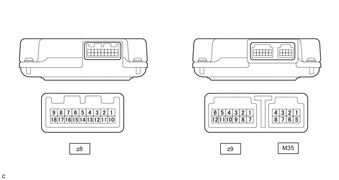
HYBRID VEHICLE CONTROL ECU
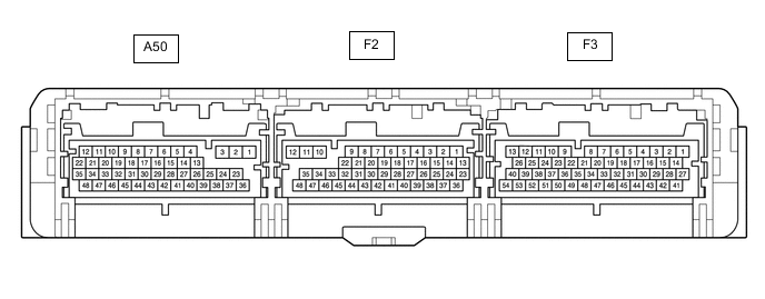
Terminal No.
(Symbol)
Wiring Color Input/Output Terminal Description Condition Specified Condition A50-4 (HMCH) - F3-3 (E1) B - W-B IN/OUT CAN Communication signal Power switch on (IG) Pulse generation
(Waveform 1)
A50-5 (MREL) - F3-3 (E1) BE - W-B OUT Main relay Power switch on (IG) 11 to 14 V A50-6 (HSDN) - F3-3 (E1) B - W-B OUT MG ECU shutdown signal Power switch on (READY) 0 to 1.5 V A50-7 (STP) - F3-3 (E1) SB - W-B IN Stop light switch Brake pedal depressed 11 to 14 V Brake pedal released 0 to 1.5 V A50-8 (LIN3) - F3-3 (E1) G - W-B IN/OUT LIN communication signal
(A/C inverter, auxiliary battery)
Power switch on (READY) Pulse generation A50-11 (+B1) - F3-3 (E1) L - W-B IN Power source Power switch on (IG) 11 to 14 V A50-14 (HMCL) - F3-3 (E1) W - W-B IN/OUT Communication signal Power switch on (IG) Pulse generation
(Waveform 1)
A50-20 (BL) - F3-3 (E1) SB - W-B OUT Back-up light relay Power switch on (IG), shift lever in R 11 to 14 V A50-24 (VCPA) - A50-37 (EPA) BE - L OUT Accelerator pedal sensor assembly power source (for VPA) Power switch on (IG) 4.5 to 5.5 V A50-26 (VCP2) - A50-25 (EPA2) G - W OUT Accelerator pedal sensor assembly power source (for VPA2) Power switch on (IG) 4.5 to 5.5 V A50-33 (NIWP) - F3-3 (E1) GR - W-B IN Inverter water pump assembly signal Power switch on (READY) Pulse generation
(Waveform 2)
A50-34 (IWP) - F3-3 (E1) G - W-B OUT Inverter water pump assembly signal Power switch on (READY) Pulse generation
(Waveform 2)
A50-36 (VPA) - A50-37 (EPA) GR - L IN Accelerator pedal sensor assembly (for accelerator pedal position detection) Power switch on (IG), accelerator pedal released 0.4 to 1.4 V Power switch on (IG), engine stopped, shift position P, accelerator pedal fully depressed 2.6 to 4.5 V A50-38 (VPA2) - A50-25 (EPA2) B - W IN Accelerator pedal sensor assembly (for accelerator pedal sensor malfunction detection) Power switch on (IG), accelerator pedal released 1.0 to 2.2 V Power switch on (IG), engine stopped, shift position P, accelerator pedal fully depressed 3.4 to 5.3 V A50-40 (TTA) - A50-39 (ETTA) SB - P IN Transmission fluid temperature sensor Power switch on (IG), temperature 25°C (77°F) 3.6 to 4.6 V Power switch on (IG), temperature 60°C (140°F) 2.2 to 3.2 V A50-46 (MMT) - A50-45 (MMTG) L - BR IN Motor temperature sensor Power switch on (IG), temperature 25°C (77°F) 3.6 to 4.6 V Power switch on (IG), temperature 60°C (140°F) 2.2 to 3.2 V A50-48 (GMT) - A50-47 (GMTG) LG - R IN Generator temperature sensor Power switch on (IG), temperature 25°C (77°F) 3.6 to 4.6 V Power switch on (IG), temperature 60°C (140°F) 2.2 to 3.2 V F2-5 (ILK) - F3-3 (E1) V - W-B IN Interlock switch Power switch on (IG), service plug grip installed correctly 0 to 1.5 V Power switch on (IG), service plug grip not installed 11 to 14 V F2-7 (CA3P) - F3-3 (E1) G - W-B IN/OUT CAN communication signal Power switch on (IG) Pulse generation
(Waveform 3)
F2-8 (CA1L) - F3-3 (E1) W - W-B IN/OUT CAN communication signal Power switch on (IG) Pulse generation
(Waveform 4)
F2-13 (SMRG) - F2-12 (E01) P - W-B OUT System main relay operation signal Power switch on (IG)→Power switch on (READY) Pulse generation
(Waveform 5)
F2-15 (SMRP) - F2-12 (E01) LG - W-B OUT System main relay operation signal Power switch on (IG)→Power switch on (READY) Pulse generation
(Waveform 5)
F2-16 (SMRB) - F2-12 (E01) BE - W-B OUT System main relay operation signal Power switch on (IG)→Power switch on (READY) Pulse generation
(Waveform 5)
F2-20 (CA3N) - F3-3 (E1) W - W-B IN/OUT CAN communication signal Power switch on (IG) Pulse generation
(Waveform 3)
F2-21 (CA1H) - F3-3 (E1) L - W-B IN/OUT CAN communication signal Power switch on (IG) Pulse generation
(Waveform 4)
F2-35 (IG2) - F3-3 (E1) BE - W-B IN Power source Power switch on (IG) 11 to 14 V F2-38 (SI0) - F3-3 (E1) SB - W-B OUT Battery cooling blower operation signal Cooling fans operating Pulse generation
(Waveform 6)
Cooling fans not operating 4.5 to 5.5 V F2-41 (BTH+) - F3-3 (E1) G - W-B IN Communication signal from battery voltage sensor to hybrid vehicle control ECU Power switch on (IG) Pulse generation
(Waveform 7)
F2-42 (BTH-) - F3-3 (E1) BE - W-B IN Communication signal from battery voltage sensor to hybrid vehicle control ECU Power switch on (IG) Pulse generation
(Waveform 7)
F3-1 (+B2) - F3-3 (E1) L - W-B IN Power source Power switch on (IG) 11 to 14 V F3-4 (ST2) - F3-3 (E1) B - W-B IN Starter signal Power switch on (IG) 0 to 1.5 V F3-27 (BATT) - F3-3 (E1) GR - W-B IN Constant power source Always 10 to 14 V F3-29 (ABFS) - F3-3 (E1) B - W-B IN Airbag activation signal Power switch on (READY) Pulse generation
(Waveform 8)
F3-30 (TC) - F3-3 (E1) G - W-B IN Diagnosis terminal Power switch on (IG) 11 to 14 V F3-33 (EVSW) - F3-3 (E1) GR - W-B IN EV drive mode switch (pattern select switch assembly) signal Power switch on (IG), EV drive mode switch (pattern select switch assembly) not operated 11 to 14 V Power switch on (IG), EV drive mode switch (pattern select switch assembly) operated 0 to 1.5 V F3-37 (PDRV) - F3-3 (E1) V - W-B IN Drive mode select switch (pattern select switch assembly) signal Power switch on (IG), drive mode select switch (pattern select switch assembly) not operated 11 to 14 V Power switch on (IG), drive mode select switch (pattern select switch assembly) operated 0 to 1.5 V F3-44 (IGB) - F3-3 (E1) LG - W-B IN Power source Power switch on (IG) 11 to 14 V F3-46 (VSI4) - F3-49 (E2X2) W - BE IN Shift sensor (VSX4) Power switch on (IG), shift lever in home position 0.68 to 1.62 V Power switch on (IG), shift lever in D 4.47 to 4.75 V Power switch on (IG), shift lever in N 3.53 to 4.47 V Power switch on (IG), shift lever in R 2.75 to 3.52 V Power switch on (IG), shift lever in B 0.40 to 0.67 V F3-48 (VSI3) - F3-49 (E2X2) B - BE IN Shift sensor (VSX3) Power switch on (IG), shift lever in home position 1.63 to 2.70 V Power switch on (IG), shift lever in D 3.53 to 4.17 V Power switch on (IG), shift lever in N 2.45 to 3.52 V Power switch on (IG), shift lever in R 1.63 to 2.45 V Power switch on (IG), shift lever in B 0.98 to 2.45 V F3-50 (VSI2) - F3-51 (E2X1) R - GR IN Shift sensor (VSX2) Power switch on (IG), shift lever in home position 2.45 to 3.52 V Power switch on (IG), shift lever in D 2.70 to 3.52 V Power switch on (IG), shift lever in N 1.63 to 2.70 V Power switch on (IG), shift lever in R 0.98 to 1.62 V Power switch on (IG), shift lever in B 1.63 to 2.45 V F3-52 (VSI1) - F3-51 (E2X1) BR - GR IN Shift sensor (VSX1) Power switch on (IG), shift lever in home position 3.53 to 4.47 V Power switch on (IG), shift lever in D 1.63 to 2.40 V Power switch on (IG), shift lever in N 0.68 to 1.62 V Power switch on (IG), shift lever in R 0.40 to 0.67 V Power switch on (IG), shift lever in B 2.75 to 3.52 V F3-53 (VCX2) - F3-49 (E2X2) L - BE OUT Shift sensor power source (VCX2) Power switch on (IG) 4.5 to 5.5 V F3-54 (VCX1) - F3-51 (E2X1) V - GR OUT Shift sensor power source (VCX1) Power switch on (IG) 4.5 to 5.5 V
-
Oscilloscope waveforms
Tech Tips
Oscilloscope waveform samples are provided here for informational purposes. Noise and fluttering waveforms have been omitted.
-
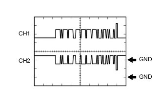
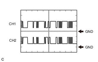
Waveform 1 (CAN communication signal)
Item Content Terminal CH1: A50-4 (HMCH) - F3-3 (E1)
CH2: A50-14 (HMCL) - F3-3 (E1)
Equipment Setting 1 V/DIV., 50 μs./DIV. Condition Power switch on (IG) Tech Tips
The waveform will vary depending on the content of the digital communication (digital signal).
-
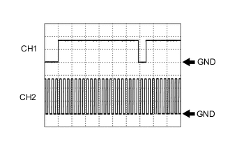
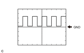
Waveform 2 (Inverter water pump assembly signal)
Item Content Terminal CH1: A50-34 (IWP) - F3-3 (E1)
CH2: A50-33 (NIWP) - F3-3 (E1)
Equipment Setting 5 V/DIV., 20 ms./DIV. Condition Power switch on (READY) -

Waveform 3 (CAN communication signal)
Item Content Terminal CH1: F2-7 (CA3P) - F3-3 (E1)
CH2: F2-20 (CA3N) - F3-3 (E1)
Equipment Setting 1 V/DIV., 50 μs./DIV. Condition Power switch on (IG) Tech Tips
The waveform will vary depending on the content of the digital communication (digital signal).
-
Waveform 4 (CAN communication signal)
Item Content Terminal CH1: F2-21 (CA1H) - F3-3 (E1)
CH2: F2-8 (CA1L) - F3-3 (E1)
Equipment Setting 1 V/DIV., 50 μs./DIV. Condition Power switch on (IG) Tech Tips
The waveform will vary depending on the content of the digital communication (digital signal).
-
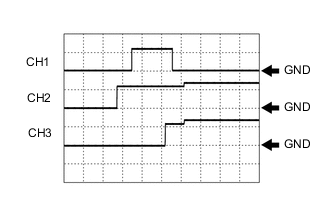
Waveform 5 (system main relay operation signal)
Item Content Terminal CH1: F2-15 (SMRP) - F2-12 (E01)
CH2: F2-16 (SMRB) - F2-12 (E01)
CH3: F2-13 (SMRG) - F2-12 (E01)
Equipment Setting 10 V/DIV., 200 ms./DIV. Condition Power switch on (IG) → Power switch on (READY) -
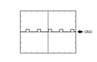
Waveform 6 (HV battery blower fan operation signal)
Item Content Terminal F2-38 (SI0) - F3-3 (E1) Equipment Setting 10 V/DIV., 1 ms./DIV. Condition Cooling fans operating Tech Tips
The waveform will vary with the operating speed of the battery cooling blower assembly.
-
Waveform 7 (communication signal from battery voltage sensor to hybrid vehicle control ECU)
Item Content Terminal CH1: F2-41 (BTH+) - F3-3 (E1)
CH2: F2-42 (BTH-) - F3-3 (E1)
Equipment Setting 2 V/DIV., 500 μs./DIV. Condition Power switch on (IG) Tech Tips
The waveform will vary depending on the content of the digital communication (digital signal).
-
Waveform 8 (airbag activation signal)
Item Content Terminal F3-29 (ABFS) - F3-3 (E1) Equipment Setting 5 V/DIV., 125 ms./DIV. Condition Power switch on (READY)
-
-
-
BATTERY VOLTAGE SENSOR
Terminal No.
(Symbol)
Wiring Color Input/Output Terminal Description Condition Specified Condition z9-1 (TC0) - z9-7 (GC0) G - G IN Intake air temperature sensor HV battery intake air temperature: -40 to 90°C (-40 to 194°F) 4.8 (-40°C (-40°F)) to 1.0 V (90°C (194°F)) z9-2 (TB2) - z9-8 (GB2) R - R IN Battery temperature sensor 2 HV battery temperature: -40 to 90°C (-40 to 194°F) 4.8 (-40°C (-40°F)) to 1.0 V (90°C (194°F)) z9-3 (TB1) - z9-9 (GB1) W - W IN Battery temperature sensor 1 HV battery temperature: -40 to 90°C (-40 to 194°F) 4.8 (-40°C (-40°F)) to 1.0 V (90°C (194°F)) z9-4 (TB0) - z9-10 (GB0) L - L IN Battery temperature sensor 0 HV battery temperature: -40 to 90°C (-40 to 194°F) 4.8 (-40°C (-40°F)) to 1.0 V (90°C (194°F)) z9-5 (IB0) - z9-12 (GIB) Y - B IN Current sensor Power switch on (READY) 0.5 to 4.5 V z9-6 (VIB) - z9-12 (GIB) BR - B OUT Power source for battery current sensor Power switch on (IG) 4.5 to 5.5 V M35-1 (IGCT) - M35-5 (GND) SB - W-B IN Control signal Power switch on (READY) 11 to 14 V M35-2 (BTH+) - M35-5 (GND) R - W-B OUT Serial communication Power switch on (IG) Pulse generation
(waveform 1)
M35-3 (BTH-) - M35-5 (GND) W - W-B OUT Serial communication Power switch on (IG) Pulse generation
(waveform 2)
M35-5 (GND) - Body ground W-B - Ground Always (continuity check) Below 1 Ω M35-8 (FP0) - M35-5 (GND) B - W-B IN Battery cooling blower No. 0 monitor signal Cooling blower stopped 0 Hz Cooling blower activated Pulse generation
(waveform 3)
-
Oscilloscope waveforms
Tech Tips
Oscilloscope waveform samples are provided here for informational purposes. Noise and fluttering waveforms have been omitted.
-
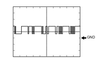
Waveform 1 (Serial communication)
Item Content Terminal M35-2 (BTH+) - M35-5 (GND) Equipment Setting 2 V/DIV., 500 μs/DIV. Condition Power switch on (IG) Tech Tips
The waveform will vary depending on the content of the digital communication (digital signal).
-
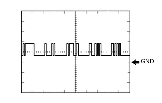
Waveform 2 (Serial communication)
Item Content Terminal M35-3 (BTH-) - M35-5 (GND) Equipment Setting 2 V/DIV., 500 μs/DIV. Condition Power switch on (IG) Tech Tips
The waveform will vary depending on the content of the digital communication (digital signal).
-
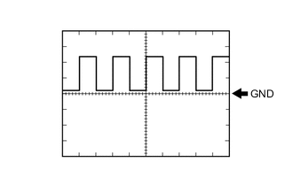
Waveform 3 (Battery cooling blower No. 0 monitor signal)
Item Content Terminal M35-8 (FP0) - M35-5 (GND) Equipment Setting 2 V/DIV., 2 ms/DIV. Condition Battery cooling blower assembly (No. 0) operating (Active Test of cooling fan being performed) Tech Tips
The frequency of the waveform will vary with the operating speed of the battery cooling blower assembly (No. 0).
-
-