SFI SYSTEM(w/ Canister Pump Module), Diagnostic DTC:P060796
| DTC Code | DTC Name |
|---|---|
| P060796 | Control Module Performance Bank 1 Component Internal Failure |
MONITOR DESCRIPTION
The ECM continuously monitors its internal processors (CPUs) and heated oxygen sensor transistors. This self-check ensures that the ECM is functioning properly.
| DTC No. | Detection Item | DTC Detection Condition | Trouble Area | MIL | Memory | Note |
|---|---|---|---|---|---|---|
| P060796 | Control Module Performance Bank 1 Component Internal Failure | Either of the following condition is met (1 trip detection logic):
|
|
Comes on | DTC stored | SAE Code: P0607 |
MONITOR STRATEGY
| Required Sensors/Components (Main) | ECM |
| Required Sensors/Components (Related) | Heated oxygen sensor |
| Frequency of Operation | Continuous |
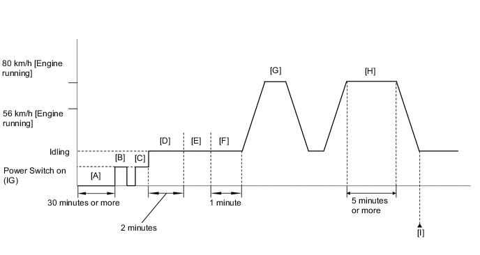
CONFIRMATION DRIVING PATTERN
-
Stop the engine for 30 minutes or more [A].
-
Connect the GTS to the DLC3.
-
Turn the power switch on (IG) [B].
-
Turn the GTS on.
-
Clear the DTCs (even if no DTCs are stored, perform the clear DTC procedure).
-
Turn the power switch off and wait for at least 30 seconds.
-
Turn the power switch on (IG) [C].
-
Turn the GTS on.
-
Put the engine in Inspection Mode (Maintenance Mode).
-
Start the engine and wait 2 minutes [D].
-
Warm up the engine until the engine coolant temperature is 75°C (167°F) or higher [E].
-
Idle the engine for 1 minute [F].
-
With the engine running, accelerate the vehicle to 80 km/h (50 mph) and stop the vehicle [G].
CAUTION:
When performing the confirmation driving pattern, obey all speed limits and traffic laws.
Tech Tips
If the engine stops, further depress the accelerator pedal to restart the engine.
-
With the engine running, drive the vehicle at 56 to 80 km/h (35 to 50 mph) for 5 minutes or more [H].
CAUTION:
When performing the confirmation driving pattern, obey all speed limits and traffic laws.
Tech Tips
If the engine stops, further depress the accelerator pedal to restart the engine.
-
Enter the following menus: Powertrain / Engine / Trouble Codes [I].
-
Read the pending DTCs.
Tech Tips
-
If a pending DTC is output, the system is malfunctioning.
-
If a pending DTC is not output, perform the following procedure.
-
-
Enter the following menus: Powertrain / Engine / Utility / All Readiness.
-
Input the DTC: P060796, P013611, P013613, P013614, P013615, P013617 or P013623.
-
Check the DTC judgment result.
GTS Display Description NORMAL
-
DTC judgment completed
-
System normal
ABNORMAL
-
DTC judgment completed
-
System abnormal
INCOMPLETE
-
DTC judgment not completed
-
Perform driving pattern after confirming DTC enabling conditions
N/A
-
Unable to perform DTC judgment
-
Number of DTCs which do not fulfill DTC preconditions has reached ECU memory limit
Tech Tips
-
If the judgment result is NORMAL, the system is normal.
-
If the judgment result is ABNORMAL, the system is malfunctioning.
-
If the judgment result is INCOMPLETE or N/A, perform steps [E] through [I] again.
-
CAUTION / NOTICE / HINT
Tech Tips
Read freeze frame data using the GTS. The ECM records vehicle and driving condition information as freeze frame data the moment a DTC is stored. When troubleshooting, freeze frame data can help determine if the vehicle was moving or stationary, if the engine was warmed up or not, if the air fuel ratio was lean or rich, and other data from the time the malfunction occurred.
PROCEDURE
-
CHECK ANY OTHER DTCS OUTPUT (IN ADDITION TO DTC P060796)
-
Connect the GTS to the DLC3.
-
Turn the power switch on (IG).
-
Turn the GTS on.
-
Enter the following menus: Powertrain / Engine / Trouble Codes.
-
Read the DTCs.
Powertrain > Engine > Trouble CodesResult Result Proceed to P060796 and P013611, P013613, P013614, P013615, P013617 or P013623 are output A P060796 is output B
A 
GO TO STEP 5 Click here
B 
-
-
CHECK FOR EXHAUST GAS LEAK
-
Connect the GTS to the DLC3.
-
Turn the power switch on (IG).
-
Turn the GTS on.
-
Put the engine in Inspection Mode (Maintenance Mode).
Powertrain > Hybrid Control > UtilityTester Display Inspection Mode -
Start the engine.
-
Allow the engine to idle, and then rev the engine.
-
Check for exhaust gas leaks around the heated oxygen sensor.
If any exhaust gas leaks are present, repair them and proceed to "Perform Confirmation Driving Pattern". If no exhaust gas leaks are present, proceed to "Perform Confirmation Driving Pattern".
Tech Tips
-
If no exhaust gas leaks are present, there may be a malfunction in the heated oxygen sensor circuit.
-
If any exhaust gas leaks are present around the heated oxygen sensor, noise appears in the output voltage of the heated oxygen sensor.
-
Perform "Inspection After Repair" after repairing or replacing the exhaust system.
Result Proceed to NEXT -
NEXT
-
-
CLEAR DTC
-
Connect the GTS to the DLC3.
-
Turn the power switch on (IG).
-
Turn the GTS on.
-
Clear the DTCs.
Powertrain > Engine > Clear DTCs -
Turn the power switch off and wait for at least 30 seconds.
Result Proceed to NEXT
NEXT
-
-
PERFORM CONFIRMATION DRIVING PATTERN
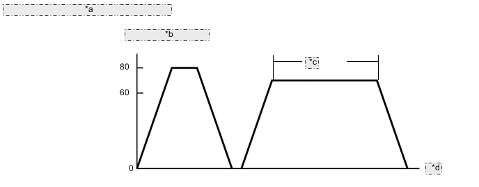
*a Engine Coolant Temperature: 75°C or higher *b km/h [Engine running] *c 5 minutes *d Time
-
Connect the GTS to the DLC3.
-
Turn the power switch on (IG).
-
Turn the GTS on.
-
Put the engine in Inspection Mode (Maintenance Mode).
Powertrain > Hybrid Control > UtilityTester Display Inspection Mode -
Start the engine.
-
Warm up the engine until the engine coolant temperature is 75°C (167°F) or higher.
-
Perform the driving pattern.
CAUTION:
When performing the confirmation driving pattern, obey all speed limits and traffic laws.
Tech Tips
If the engine stops, further depress the accelerator pedal to restart the engine.
-
With the engine running, accelerate the vehicle until 80 km/h (50 mph) and stop the vehicle.
-
With the engine running, drive the vehicle between 60 to 80 km/h (37 to 50 mph) for 5 minutes.
-
-
Enter the following menus: Powertrain / Engine / Trouble Codes.
-
Read the DTCs.
Powertrain > Engine > Trouble CodesResult Result Proceed to P013611, P013613, P013614, P013615, P013617, P013623 and/or P060796 are output A Only P060796 is output B DTCs are not output C
B 
REPLACE ECM Click here
C
GO TO STEP 58 Click here
A
-
-
READ OUTPUT DTC (DTC P013611, P013613, P013614, P013615, P013617 OR P013623)
-
Connect the GTS to the DLC3.
-
Turn the power switch on (IG).
-
Turn the GTS on.
-
Enter the following menus: Powertrain / Engine / Trouble Codes.
-
Read the DTCs.
Powertrain > Engine > Trouble CodesResult Result Proceed to P013615 is output A P013614 or P013617 is output B P013611 or P013613 is output C P013623 is output D
B
GO TO STEP 44 Click here
C
PERFORM ACTIVE TEST USING GTS (CONTROL THE INJECTION VOLUME FOR A/F SENSOR) Click here
D
CHECK FOR EXHAUST GAS LEAK Click here
A
-
-
INSPECT HEATED OXYGEN SENSOR (CHECK FOR SHORT)
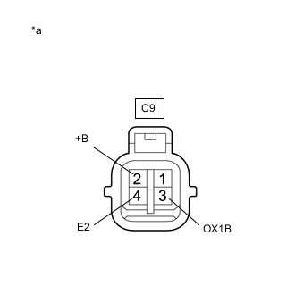
*a Component without harness connected
(Heated Oxygen Sensor)
-
Disconnect the heated oxygen sensor connector.
-
Measure the resistance according to the value(s) in the table below.
Standard Resistance Tester Connection Condition Specified Condition C9-2 (+B) - C9-4 (E2) Always 10 kΩ or higher C9-2 (+B) - C9-3 (OX1B) Always 10 kΩ or higher Result Proceed to OK NG
NG
REPLACE HEATED OXYGEN SENSOR Click here
OK
-
-
CHECK HARNESS AND CONNECTOR (CHECK FOR SHORT)
-
Turn the power switch off and wait for 5 minutes or more.
-
Disconnect the ECM connector.
-
Measure the resistance according to the value(s) in the table below.
Standard Resistance Tester Connection Condition Specified Condition C31-56 (HT1B) - C31-99 (OX1B) Always 10 kΩ or higher Result Proceed to OK NG
NG
REPAIR OR REPLACE HARNESS OR CONNECTOR (HEATED OXYGEN SENSOR - ECM) Click here
OK
-
-
REPLACE ECM
-
Replace the ECM.
Tech Tips
Result Proceed to NEXT
NEXT
GO TO STEP 58 Click here
-
-
REPAIR OR REPLACE HARNESS OR CONNECTOR (HEATED OXYGEN SENSOR - ECM)
-
Repair or replace the wire harness or connector.
Result Proceed to NEXT
NEXT
GO TO STEP 58 Click here
-
-
REPLACE HEATED OXYGEN SENSOR
-
Replace the heated oxygen sensor.
Tech Tips
-
Perform "Inspection After Repair" after replacing the heated oxygen sensor.
Result Proceed to NEXT
NEXT
GO TO STEP 58 Click here
-
-
PERFORM ACTIVE TEST USING GTS (CONTROL THE INJECTION VOLUME FOR A/F SENSOR)
-
Connect the GTS to the DLC3.
-
Turn the power switch on (IG).
-
Turn the GTS on.
-
Put the engine in Inspection Mode (Maintenance Mode).
Powertrain > Hybrid Control > UtilityTester Display Inspection Mode -
Start the engine and warm it up until the engine coolant temperature is 75°C (167°F) or higher.
-
Idle the engine for 5 minutes or more with park (P) selected.
-
Enter the following menus: Powertrain / Engine / Active Test / Control the Injection Volume for A/F Sensor / Data List / Injection Volume and O2 Sensor Voltage B1S2.
Powertrain > Engine > Active TestActive Test Display Control the Injection Volume for A/F Sensor Data List Display Injection Volume O2 Sensor Voltage B1S2 -
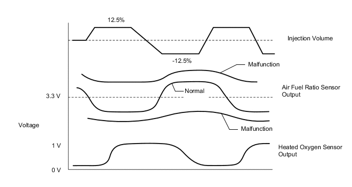
Change the fuel injection volume using the GTS, and monitor the output voltage of the heated oxygen sensor (O2 Sensor Voltage B1S2) displayed on the GTS.
Tech Tips
-
The Active Test "Control the Injection Volume for A/F Sensor" can be used to lower the fuel injection volume by 12.5% or increase the injection volume by 12.5%.
-
The heated oxygen sensor has a maximum output delay of approximately 20 seconds.
Standard Voltage Fluctuates between 0.4 V or less, and 0.55 V or higher. Result Result Proceed to The value of O2 Sensor Voltage B1S2 fluctuates between 0.4 V or less, and 0.55 V or more OK Other than above NG -
NG
CHECK FOR EXHAUST GAS LEAK Click here
OK
-
-
PERFORM ACTIVE TEST USING GTS (CONTROL THE INJECTION VOLUME FOR A/F SENSOR)
-
Connect the GTS to the DLC3.
-
Turn the power switch on (IG).
-
Turn the GTS on.
-
Put the engine in Inspection Mode (Maintenance Mode).
Powertrain > Hybrid Control > UtilityTester Display Inspection Mode -
Start the engine and warm it up until the engine coolant temperature is 75°C (167°F) or higher.
-
Idle the engine for 5 minutes or more with park (P) selected.
-
Enter the following menus: Powertrain / Engine / Active Test / Control the Injection Volume for A/F Sensor / Data List / Injection Volume, A/F (O2) Sensor Voltage B1S1 and O2 Sensor Voltage B1S2.
Powertrain > Engine > Active TestActive Test Display Control the Injection Volume for A/F Sensor Data List Display Injection Volume A/F (O2) Sensor Voltage B1S1 O2 Sensor Voltage B1S2 -
Change the fuel injection volume using the GTS, and monitor the output voltage of the air fuel ratio sensor (A/F (O2) Sensor Voltage B1S1) and heated oxygen sensor (O2 Sensor Voltage B1S2) displayed on the GTS.
Tech Tips
-
The Active Test "Control the Injection Volume for A/F Sensor" can be used to lower the fuel injection volume by 12.5% or increase the injection volume by 12.5%.
-
The air fuel ratio sensor is displayed as A/F (O2) Sensor Voltage B1S1, and the heated oxygen sensor is displayed as O2 Sensor Voltage B1S2 on the GTS.
-
The air fuel ratio sensor has an output delay of a few seconds and the heated oxygen sensor has a maximum output delay of approximately 20 seconds.
-
If the sensor output voltage does not change (almost no reaction) while performing the Active Test, the sensor may be malfunctioning.
Result Result Proceed to The value of A/F (O2) Sensor Voltage B1S1 alternates between more and less than 3.3 V A The value of A/F (O2) Sensor Voltage B1S1 remains more than 3.3 V B The value of A/F (O2) Sensor Voltage B1S1 remains less than 3.3 V C Tech Tips
A normal heated oxygen sensor voltage (O2 Sensor Voltage B1S2) reacts in accordance with increases and decreases in the fuel injection volume. When the air fuel ratio sensor voltage (A/F (O2) Sensor Voltage B1S1) remains at either less or higher than 3.3 V despite the heated oxygen sensor indicating a normal reaction, the air fuel ratio sensor is malfunctioning.
-
B
GO TO STEP 40 Click here
C
PERFORM ACTIVE TEST USING GTS (CONTROL THE EGR STEP POSITION) Click here
A
-
-
CHECK PCV HOSE CONNECTIONS
-
Check the PCV hose connections.
Tech Tips
OK PCV valve and hose are connected correctly and are not damaged. Result Proceed to OK NG
NG
REPAIR OR REPLACE PCV HOSE Click here
OK
-
-
CHECK INTAKE SYSTEM
-
Check the intake system for vacuum leaks.
OK No leaks from intake system. Result Proceed to OK NG
NG
REPAIR OR REPLACE INTAKE SYSTEM Click here
OK
-
-
PERFORM ACTIVE TEST USING GTS (CONTROL THE INJECTION VOLUME FOR A/F SENSOR)
-
Connect the GTS to the DLC3.
-
Turn the power switch on (IG).
-
Turn the GTS on.
-
Put the engine in Inspection Mode (Maintenance Mode).
Powertrain > Hybrid Control > UtilityTester Display Inspection Mode -
Start the engine and warm it up until the engine coolant temperature is 75°C (167°F) or higher.
-
Idle the engine for 5 minutes or more with park (P) selected.
-
Enter the following menus: Powertrain / Engine / Active Test / Control the Injection Volume for A/F Sensor / Data List / Injection Volume, A/F (O2) Sensor Voltage B1S1 and O2 Sensor Voltage B1S2.
Powertrain > Engine > Active TestActive Test Display Control the Injection Volume for A/F Sensor Data List Display Injection Volume A/F (O2) Sensor Voltage B1S1 O2 Sensor Voltage B1S2 -
Change the fuel injection volume using the GTS, and monitor the output voltage of the air fuel ratio sensor (A/F (O2) Sensor Voltage B1S1) and heated oxygen sensor (O2 Sensor Voltage B1S2) displayed on the GTS.
Tech Tips
-
The Active Test "Control the Injection Volume for A/F Sensor" can be used to lower the fuel injection volume by 12.5% or increase the injection volume by 12.5%.
-
The air fuel ratio sensor is displayed as A/F (O2) Sensor Voltage B1S1, and the heated oxygen sensor is displayed as O2 Sensor Voltage B1S2 on the GTS.
-
The air fuel ratio sensor has an output delay of a few seconds and the heated oxygen sensor has a maximum output delay of approximately 20 seconds.
-
If the sensor output voltage does not change (almost no reaction) while performing the Active Test, the sensor may be malfunctioning.
Standard GTS Display (Sensor) Injection Volume Status Voltage A/F (O2) Sensor Voltage B1S1
(Air fuel ratio)
12.5% Rich Below 3.1 V -12.5% Lean Higher than 3.4 V O2 Sensor Voltage B1S2
(Heated oxygen)
12.5% Rich Higher than 0.55 V -12.5% Lean Below 0.4 V Result Status A/F (O2) Sensor Voltage B1S1 Status O2 Sensor Voltage B1S2 Air Fuel Ratio Condition and Air Fuel Ratio Sensor Condition Suspected Trouble Area Proceed to Lean/Rich Lean/Rich Normal - A Lean Lean Actual air fuel ratio lean
-
PCV valve and hose
-
PCV hose connections
-
Fuel injector assembly blockage
-
Gas leak from exhaust system
-
Intake system
-
Fuel pressure
-
Mass air flow meter sub-assembly
-
Engine coolant temperature sensor
-
EGR valve assembly
Rich Rich Actual air fuel ratio rich
-
Fuel injector assembly leak or blockage
-
Gas leak from exhaust system
-
Ignition system
-
Fuel pressure
-
Mass air flow meter sub-assembly
-
Engine coolant temperature sensor
Lean Lean/Rich Air fuel ratio sensor malfunction
-
Air fuel ratio sensor
B Rich Lean/Rich Air fuel ratio sensor malfunction
-
Air fuel ratio sensor
-
Lean: While performing the Active Test "Control the Injection Volume for A/F Sensor", the air fuel ratio sensor output voltage (A/F (O2) Sensor Voltage B1S1) is consistently higher than 3.4 V, and the heated oxygen sensor output voltage (O2 Sensor Voltage B1S2) is consistently below 0.4 V.
-
Rich: While performing the Active Test "Control the Injection Volume for A/F Sensor", the air fuel ratio sensor output voltage (A/F (O2) Sensor Voltage B1S1) is consistently below 3.1 V, and the heated oxygen sensor output voltage (O2 Sensor Voltage B1S2) is consistently higher than 0.55 V.
-
Lean/Rich: While performing the Active Test "Control the Injection Volume for A/F Sensor", the output voltage of the fuel ratio sensor (A/F (O2) Sensor Voltage B1S1) or heated oxygen sensor (O2 Sensor Voltage B1S2) alternates correctly.
Tech Tips
Refer to "Data List / Active Test" [A/F (O2) Sensor Voltage B1S1 and O2 Sensor Voltage B1S2].
-
B
INSPECT AIR FUEL RATIO SENSOR (HEATER RESISTANCE) Click here
A
-
-
READ VALUE USING GTS (COOLANT TEMPERATURE)
-
Connect the GTS to the DLC3.
-
Turn the power switch on (IG).
-
Turn the GTS on.
-
Enter the following menus: Powertrain / Engine / Data List / Coolant Temperature.
Powertrain > Engine > Data ListTester Display Coolant Temperature -
Read the Data List twice, when the engine is both cold and warmed up.
Standard GTS Display Condition Specified Condition Coolant Temperature Cold engine Same as ambient air temperature Warm engine Between 75 and 100°C (167 and 212°F) Result Proceed to OK NG
NG
REPLACE ENGINE COOLANT TEMPERATURE SENSOR Click here
OK
-
-
PERFORM ACTIVE TEST USING GTS (CONTROL THE EGR STEP POSITION)
-
Connect the GTS to the DLC3.
-
Turn the power switch on (IG).
-
Turn the GTS on.
-
Put the engine in Inspection Mode (Maintenance Mode).
Powertrain > Hybrid Control > UtilityTester Display Inspection Mode -
Start the engine and warm it up until the engine coolant temperature is 75°C (167°F) or higher.
Tech Tips
The A/C switch and all accessories should be off.
-
Enter the following menus: Powertrain / Engine / Active Test / Control the EGR Step Position / Data List / Intake Manifold Absolute Pressure, EGR Step Position and Engine Independent.
Powertrain > Engine > Active TestActive Test Display Control the EGR Step Position Data List Display Intake Manifold Absolute Pressure EGR Step Position Engine Independent -
Confirm that the value of Data List item Engine Independent is "Operate" then check the value of Intake Manifold Absolute Pressure while performing the Active Test.
Note
-
Do not leave the EGR valve open for 10 seconds or more during the Active Test.
-
Be sure to return the EGR valve to step 0 when the Active Test is completed.
-
Do not open the EGR valve 30 steps or more during the Active Test.
OK The value of Intake Manifold Absolute Pressure changes in response to the EGR step position when the value of Engine Independent is "Operate". Standard - Control the EGR Step Position (Active Test) 0 Steps 0 to 30 Steps Intake Manifold Absolute Pressure
(Data List)
(EGR valve is fully closed) Intake Manifold Absolute Pressure value is at least +10 kPa (1.45 psi) higher than when EGR valve is fully closed Tech Tips
-
If the value of Data List item Engine Independent is "Not Opr" when the engine is idling, charge control is being performed. Perform the Active Test after charge control is complete ("Operate" is displayed).
-
While performing the Active Test, if the increase in the value of Intake Manifold Absolute Pressure is small, the EGR valve assembly may be malfunctioning.
-
Even if the EGR valve assembly is malfunctioning, rough idling or an increase in the value of Intake Manifold Absolute Pressure may occur while performing the Active Test. However, the amount that the value of Intake Manifold Absolute Pressure increases will be smaller than normal.
Result Result Proceed to The value of Intake Manifold Absolute Pressure increases by 10 kPa(abs) or more, compared to when the EGR valve was fully closed (0 step) OK Other than above NG Tech Tips
10 kPa = 1.45 psi
-
OK
GO TO STEP 19 Click here
NG
-
-
INSPECT EGR VALVE ASSEMBLY
-
Remove the EGR valve assembly.
Tech Tips
-
Check if the EGR valve is stuck open.
OK EGR valve is tightly closed. Result Proceed to OK NG
NG
REPLACE EGR VALVE ASSEMBLY Click here
OK
-
-
READ VALUE USING GTS (MASS AIR FLOW SENSOR)
-
Connect the GTS to the DLC3.
-
Turn the power switch on (IG).
-
Turn the GTS on.
-
Put the engine in Inspection Mode (Maintenance Mode).
Powertrain > Hybrid Control > UtilityTester Display Inspection Mode -
Start the engine.
-
Enter the following menus: Powertrain / Engine / Data List / Engine Speed, Mass Air Flow Sensor and Coolant Temperature.
Powertrain > Engine > Data ListTester Display Engine Speed Mass Air Flow Sensor Coolant Temperature -
Allow the engine to idle until Coolant Temperature is 75°C (167°F) or higher.
-
Read Mass Air Flow Sensor with the engine speed at 2500 rpm.
Tech Tips
During charge control, the engine speed is set at idle. Therefore, the engine speed will not increase when the accelerator pedal is depressed. In this case, read the Data List after charge control has completed.
Standard GTS Display Condition Specified Condition Mass Air Flow Sensor Engine warmed up
Shift position: P
A/C: Off
Engine Speed: 2500 rpm
Between 4.5 and 8.5 gm/sec Result Result Proceed to The value of Mass Air Flow Sensor is between 4.5 gm/sec and 8.5 gm/sec OK Other than above NG
NG
GO TO STEP 24 Click here
OK
-
-
CHECK FUEL PRESSURE
-
Check the fuel pressure.
Result Proceed to OK NG
NG
REPAIR OR REPLACE FUEL SYSTEM Click here
OK
-
-
CHECK FOR EXHAUST GAS LEAK
-
Check for exhaust gas leaks.
OK No gas leaks in exhaust system. Result Proceed to OK NG
NG
REPAIR OR REPLACE EXHAUST SYSTEM Click here
OK
-
-
INSPECT IGNITION SYSTEM
-
Inspect the ignition system.
Tech Tips
If the spark plugs or ignition system malfunctions, engine misfire may occur. The misfire count can be read using the GTS. Enter the following menus: Powertrain / Engine / Data List / Misfire Count Cylinder #1 to Misfire Count Cylinder #4.
Result Proceed to OK NG
NG
REPAIR OR REPLACE IGNITION SYSTEM Click here
OK
-
-
INSPECT FUEL INJECTOR ASSEMBLY (INJECTION AND VOLUME)
-
Check the injection and volume.
Tech Tips
-
Refer to the fuel injector assembly inspection procedure.
-
If the fuel injector assemblies malfunction, engine misfire may occur. The misfire count can be read using the GTS. Enter the following menus: Powertrain / Engine / Data List / Misfire Count Cylinder #1 to Misfire Count Cylinder #4.
Result Proceed to OK NG -
NG
REPLACE FUEL INJECTOR ASSEMBLY Click here
OK
-
-
CHECK HARNESS AND CONNECTOR (MASS AIR FLOW METER SUB-ASSEMBLY CONNECTOR CONNECTION)
-
Check the connection and terminal contact pressure of connectors and wire harnesses between the mass air flow meter sub-assembly and ECM.
Result Proceed to NEXT
NEXT
GO TO STEP 58 Click here
-
-
REPLACE FUEL INJECTOR ASSEMBLY
-
Replace the fuel injector assembly.
Tech Tips
-
Perform "Inspection After Repair" after replacing the fuel injector assembly.
Result Proceed to NEXT
NEXT
GO TO STEP 58 Click here
-
-
REPAIR OR REPLACE IGNITION SYSTEM
-
Repair or replace the ignition system.
Tech Tips
Perform "Inspection After Repair" after repairing or replacing the ignition system.
Result Proceed to NEXT
NEXT
GO TO STEP 58 Click here
-
-
REPAIR OR REPLACE EXHAUST SYSTEM
-
Repair or replace the exhaust system.
Tech Tips
Perform "Inspection After Repair" after repairing or replacing the exhaust system.
Result Proceed to NEXT
NEXT
GO TO STEP 58 Click here
-
-
REPAIR OR REPLACE FUEL SYSTEM
-
Repair or replace the fuel system.
Result Proceed to NEXT
NEXT
GO TO STEP 58 Click here
-
-
REPLACE EGR VALVE ASSEMBLY
-
Replace the EGR valve assembly.
Tech Tips
-
Perform "Inspection After Repair" after replacing the EGR valve assembly.
Result Proceed to NEXT
NEXT
GO TO STEP 58 Click here
-
-
REPLACE ENGINE COOLANT TEMPERATURE SENSOR
-
Replace the engine coolant temperature sensor.
Tech Tips
-
Perform "Inspection After Repair" after replacing the engine coolant temperature sensor.
Result Proceed to NEXT
NEXT
GO TO STEP 58 Click here
-
-
INSPECT AIR FUEL RATIO SENSOR (HEATER RESISTANCE)
-
Inspect the air fuel ratio sensor.
Result Proceed to OK NG
NG
REPLACE AIR FUEL RATIO SENSOR Click here
OK
-
-
CHECK TERMINAL VOLTAGE (POWER SOURCE OF AIR FUEL RATIO SENSOR)
-
Disconnect the air fuel ratio sensor connector.
-
Turn the power switch on (IG).
-
Measure the voltage according to the value(s) in the table below.
Standard Voltage Tester Connection Condition Specified Condition C24-2 (+B) - Body ground Power switch on (IG) 11 to 14 V Result Proceed to OK NG
NG
REPAIR OR REPLACE HARNESS OR CONNECTOR (NO. 1 INTEGRATION RELAY - AIR FUEL RATIO SENSOR) Click here
OK
-
-
CHECK HARNESS AND CONNECTOR (AIR FUEL RATIO SENSOR - ECM)
-
Disconnect the air fuel ratio sensor connector.
-
Disconnect the ECM connector.
-
Measure the resistance according to the value(s) in the table below.
Standard Resistance Tester Connection Condition Specified Condition C24-1 (HA1A) - C31-27 (HA1A) Always Below 1 Ω C24-3 (A1A+) - C31-100 (A1A+) Always Below 1 Ω C24-4 (A1A-) - C31-132 (A1A-) Always Below 1 Ω C24-1 (HA1A) or C31-27 (HA1A) - Body ground and other terminals Always 10 kΩ or higher C24-3 (A1A+) or C31-100 (A1A+) - Body ground and other terminals Always 10 kΩ or higher C24-4 (A1A-) or C31-132 (A1A-) - Body ground and other terminals Always 10 kΩ or higher Result Proceed to OK NG
NG
REPAIR OR REPLACE HARNESS OR CONNECTOR Click here
OK
-
-
REPLACE AIR FUEL RATIO SENSOR
-
Replace the air fuel ratio sensor.
Tech Tips
-
Perform "Inspection After Repair" after replacing the air fuel ratio sensor.
Result Proceed to NEXT
NEXT
GO TO STEP 58 Click here
-
-
REPAIR OR REPLACE HARNESS OR CONNECTOR
-
Repair or replace the wire harness or connector.
Result Proceed to NEXT
NEXT
GO TO STEP 58 Click here
-
-
REPAIR OR REPLACE HARNESS OR CONNECTOR (NO. 1 INTEGRATION RELAY - AIR FUEL RATIO SENSOR)
-
Repair or replace the wire harness or connector.
Result Proceed to NEXT
NEXT
GO TO STEP 58 Click here
-
-
REPLACE AIR FUEL RATIO SENSOR
-
Replace the air fuel ratio sensor.
Tech Tips
-
Perform "Inspection After Repair" after replacing the air fuel ratio sensor.
Result Proceed to NEXT
NEXT
GO TO STEP 58 Click here
-
-
REPAIR OR REPLACE INTAKE SYSTEM
-
Repair or replace the intake system.
Tech Tips
Perform "Inspection After Repair" after repairing or replacing the intake system.
Result Proceed to NEXT
NEXT
GO TO STEP 58 Click here
-
-
REPAIR OR REPLACE PCV HOSE
-
Repair or replace the PCV hose.
Result Proceed to NEXT
NEXT
GO TO STEP 58 Click here
-
-
PERFORM ACTIVE TEST USING GTS (CONTROL THE EGR STEP POSITION)
-
Connect the GTS to the DLC3.
-
Turn the power switch on (IG).
-
Turn the GTS on.
-
Put the engine in Inspection Mode (Maintenance Mode).
Powertrain > Hybrid Control > UtilityTester Display Inspection Mode -
Start the engine and warm it up until the engine coolant temperature is 75°C (167°F) or higher.
Tech Tips
The A/C switch and all accessories should be off.
-
Enter the following menus: Powertrain / Engine / Active Test / Control the EGR Step Position / Data List / Intake Manifold Absolute Pressure, EGR Step Position and Engine Independent.
Powertrain > Engine > Active TestActive Test Display Control the EGR Step Position Data List Display Intake Manifold Absolute Pressure EGR Step Position Engine Independent -
Confirm that the value of Data List item Engine Independent is "Operate" then check the value of Intake Manifold Absolute Pressure while performing the Active Test.
Note
-
Do not leave the EGR valve open for 10 seconds or more during the Active Test.
-
Be sure to return the EGR valve to step 0 when the Active Test is completed.
-
Do not open the EGR valve 30 steps or more during the Active Test.
OK The value of Intake Manifold Absolute Pressure changes in response to the EGR step position when the value of Engine Independent is "Operate". Standard - Control the EGR Step Position (Active Test) 0 Steps 0 to 30 Steps Intake Manifold Absolute Pressure
(Data List)
(EGR valve is fully closed) Intake Manifold Absolute Pressure value is at least +10 kPa (1.45 psi) higher than when EGR valve is fully closed Tech Tips
-
If the value of Data List item Engine Independent is "Not Opr" when the engine is idling, charge control is being performed. Perform the Active Test after charge control is complete ("Operate" is displayed).
-
While performing the Active Test, if the increase in the value of Intake Manifold Absolute Pressure is small, the EGR valve assembly may be malfunctioning.
-
Even if the EGR valve assembly is malfunctioning, rough idling or an increase in the value of Intake Manifold Absolute Pressure may occur while performing the Active Test. However, the amount that the value of Intake Manifold Absolute Pressure increases will be smaller than normal.
Result Result Proceed to The value of Intake Manifold Absolute Pressure increases by 10 kPa(abs) or more, compared to when the EGR valve was fully closed (0 step) OK Other than above NG Tech Tips
10 kPa = 1.45 psi
-
OK
GO TO STEP 42 Click here
NG
-
-
INSPECT EGR VALVE ASSEMBLY
-
Remove the EGR valve assembly.
Tech Tips
-
Check if the EGR valve is stuck open.
OK EGR valve is tightly closed. Result Proceed to OK NG
NG
REPLACE EGR VALVE ASSEMBLY Click here
OK
-
-
REPLACE AIR FUEL RATIO SENSOR
-
Replace the air fuel ratio sensor.
Tech Tips
-
Perform "Inspection After Repair" after replacing the air fuel ratio sensor.
Result Proceed to NEXT
NEXT
GO TO STEP 58 Click here
-
-
REPLACE EGR VALVE ASSEMBLY
-
Replace the EGR valve assembly.
Tech Tips
-
Perform "Inspection After Repair" after replacing the EGR valve assembly.
Result Proceed to NEXT
NEXT
GO TO STEP 58 Click here
-
-
CHECK FOR EXHAUST GAS LEAK
-
Check for exhaust gas leaks.
OK No gas leaks in exhaust system. Result Proceed to OK NG
NG
REPAIR OR REPLACE EXHAUST SYSTEM Click here
OK
-
-
INSPECT HEATED OXYGEN SENSOR (HEATER RESISTANCE)
-
Inspect the heated oxygen sensor.
Result Proceed to OK NG
NG
REPLACE HEATED OXYGEN SENSOR Click here
OK
-
-
CHECK HARNESS AND CONNECTOR (HEATED OXYGEN SENSOR - ECM)
-
Disconnect the heated oxygen sensor connector.
-
Disconnect the ECM connector.
-
Measure the resistance according to the value(s) in the table below.
Standard Resistance Tester Connection Condition Specified Condition C9-1 (HT1B) - C31-56 (HT1B) Always Below 1 Ω C9-3 (OX1B) - C31-99 (OX1B) Always Below 1 Ω C9-4 (E2) - C31-131 (EX1B) Always Below 1 Ω C9-1 (HT1B) or C31-56 (HT1B) - Body ground and other terminals Always 10 kΩ or higher C9-3 (OX1B) or C31-99 (OX1B) - Body ground and other terminals Always 10 kΩ or higher Result Proceed to OK NG
NG
REPAIR OR REPLACE HARNESS OR CONNECTOR Click here
OK
-
-
PERFORM ACTIVE TEST USING GTS (CONTROL THE EGR STEP POSITION)
-
Connect the GTS to the DLC3.
-
Turn the power switch on (IG).
-
Turn the GTS on.
-
Put the engine in Inspection Mode (Maintenance Mode).
Powertrain > Hybrid Control > UtilityTester Display Inspection Mode -
Start the engine and warm it up until the engine coolant temperature is 75°C (167°F) or higher.
Tech Tips
The A/C switch and all accessories should be off.
-
Enter the following menus: Powertrain / Engine / Active Test / Control the EGR Step Position / Data List / Intake Manifold Absolute Pressure, EGR Step Position and Engine Independent.
Powertrain > Engine > Active TestActive Test Display Control the EGR Step Position Data List Display Intake Manifold Absolute Pressure EGR Step Position Engine Independent -
Confirm that the value of Data List item Engine Independent is "Operate" then check the value of Intake Manifold Absolute Pressure while performing the Active Test.
Note
-
Do not leave the EGR valve open for 10 seconds or more during the Active Test.
-
Be sure to return the EGR valve to step 0 when the Active Test is completed.
-
Do not open the EGR valve 30 steps or more during the Active Test.
OK The value of Intake Manifold Absolute Pressure changes in response to the EGR step position when the value of Engine Independent is "Operate". Standard - Control the EGR Step Position (Active Test) 0 Steps 0 to 30 Steps Intake Manifold Absolute Pressure
(Data List)
(EGR valve is fully closed) Intake Manifold Absolute Pressure value is at least +10 kPa (1.45 psi) higher than when EGR valve is fully closed Tech Tips
-
If the value of Data List item Engine Independent is "Not Opr" when the engine is idling, charge control is being performed. Perform the Active Test after charge control is complete ("Operate" is displayed).
-
While performing the Active Test, if the increase in the value of Intake Manifold Absolute Pressure is small, the EGR valve assembly may be malfunctioning.
-
Even if the EGR valve assembly is malfunctioning, rough idling or an increase in the value of Intake Manifold Absolute Pressure may occur while performing the Active Test. However, the amount that the value of Intake Manifold Absolute Pressure increases will be smaller than normal.
Result Result Proceed to The value of Intake Manifold Absolute Pressure increases by 10 kPa(abs) or more, compared to when the EGR valve was fully closed (0 step) OK Other than above NG Tech Tips
10 kPa = 1.45 psi
-
OK
GO TO STEP 49 Click here
NG
-
-
INSPECT EGR VALVE ASSEMBLY
-
Remove the EGR valve assembly.
Tech Tips
-
Check if the EGR valve is stuck open.
OK EGR valve is tightly closed. Result Proceed to OK NG
NG
REPLACE EGR VALVE ASSEMBLY Click here
OK
-
-
REPLACE HEATED OXYGEN SENSOR
-
Replace the heated oxygen sensor.
Tech Tips
-
Perform "Inspection After Repair" after replacing the heated oxygen sensor.
Result Proceed to NEXT
NEXT
GO TO STEP 58 Click here
-
-
REPLACE EGR VALVE ASSEMBLY
-
Replace the EGR valve assembly.
Tech Tips
-
Perform "Inspection After Repair" after replacing the EGR valve assembly.
Result Proceed to NEXT
NEXT
GO TO STEP 58 Click here
-
-
REPAIR OR REPLACE HARNESS OR CONNECTOR
-
Repair or replace the wire harness or connector.
Result Proceed to NEXT
NEXT
GO TO STEP 58 Click here
-
-
REPLACE HEATED OXYGEN SENSOR
-
Replace the heated oxygen sensor.
Tech Tips
-
Perform "Inspection After Repair" after replacing the heated oxygen sensor.
Result Proceed to NEXT
NEXT
GO TO STEP 58 Click here
-
-
REPAIR OR REPLACE EXHAUST SYSTEM
-
Repair or replace the exhaust system.
Tech Tips
Perform "Inspection After Repair" after repairing or replacing the exhaust system.
Result Proceed to NEXT
NEXT
GO TO STEP 58 Click here
-
-
CHECK FOR EXHAUST GAS LEAK
-
Check for exhaust gas leaks.
OK No gas leaks in exhaust system. Result Proceed to OK NG
NG
REPAIR OR REPLACE EXHAUST SYSTEM Click here
OK
-
-
CHECK HARNESS AND CONNECTOR (CHECK FOR SHORT)
-
Turn the power switch off and wait for 5 minutes or more.
-
Disconnect the ECM connector.
-
Measure the resistance according to the value(s) in the table below.
Standard Resistance Tester Connection Condition Specified Condition C31-56 (HT1B) - C31-131 (OX1B) Always 10 kΩ or higher Result Proceed to OK NG
OK
GO TO STEP 58 Click here
NG
-
-
REPAIR OR REPLACE HARNESS OR CONNECTOR (HEATED OXYGEN SENSOR - ECM)
-
Repair or replace the wire harness or connector.
Result Proceed to NEXT
NEXT
GO TO STEP 58 Click here
-
-
REPAIR OR REPLACE EXHAUST SYSTEM
-
Repair or replace the exhaust system.
Tech Tips
Perform "Inspection After Repair" after repairing or replacing the exhaust system.
Result Proceed to NEXT
NEXT
-
-
CLEAR DTC
-
Connect the GTS to the DLC3.
-
Turn the power switch on (IG).
-
Turn the GTS on.
-
Clear the DTCs.
Powertrain > Engine > Clear DTCs -
Turn the power switch off and wait for 30 minutes.
Result Proceed to NEXT
NEXT
-
-
INSPECT ECM
-
Connect the GTS to the DLC3.
-
Turn the power switch on (IG).
-
Turn the GTS on.
-
Put the engine in Inspection Mode (Maintenance Mode).
Powertrain > Hybrid Control > UtilityTester Display Inspection Mode -
Start the engine and allow it to idle for 2 minutes.
-
Enter the following menus: Powertrain / Engine / Trouble Codes.
-
Read the DTCs.
Powertrain > Engine > Trouble CodesResult Result Proceed to DTCs are not output A P060796 is output B
A
END
B
REPLACE ECM Click here
-