SFI SYSTEM(w/ Canister Pump Module), Diagnostic DTC:P042000
| DTC Code | DTC Name |
|---|---|
| P042000 | Catalyst System Efficiency Below Threshold Bank 1 |
MONITOR DESCRIPTION
The ECM uses sensors mounted in front of and behind the Three-Way Catalytic Converter (TWC) to monitor its efficiency.
The first sensor, the air fuel ratio sensor, sends pre-catalyst information to the ECM. The second sensor, the heated oxygen sensor, sends post-catalyst information to the ECM.
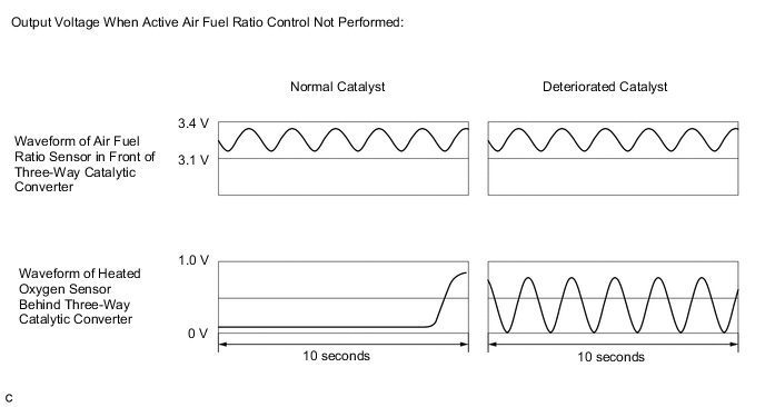
In order to detect any deterioration in the three-way catalytic converter, the ECM calculates the oxygen storage capacity of the three-way catalytic converter. This calculation is based on the output voltage of the heated oxygen sensor while performing active air fuel ratio control.
The oxygen storage capacity value is an indication of the oxygen storage capacity of the three-way catalytic converter. When the vehicle is being driven with a warm engine, active air fuel ratio control is performed for approximately 30 seconds. When it is performed, the ECM deliberately sets the air fuel ratio to lean or rich levels. If the cycle of the waveform for the heated oxygen sensor is long, the oxygen storage capacity is great. There is a direct correlation between the heated oxygen sensor and the oxygen storage capacity of the three-way catalytic converter.
The ECM uses the oxygen storage capacity value to determine the state of the three-way catalytic converter. If any deterioration has occurred, the ECM will illuminate the MIL and store a DTC.
This system determines the deterioration of the entire catalyst system (including the front and rear catalysts), by using the oxygen storage capacity value of the front catalyst, that is more sensitive than the rear catalyst, as the representative value. Therefore, be sure to replace the front and rear catalysts together when catalyst replacement is necessary.
| DTC No. | Detection Item | DTC Detection Condition | Trouble Area | MIL | Memory | Note |
|---|---|---|---|---|---|---|
| P042000 | Catalyst System Efficiency Below Threshold Bank 1 | The oxygen storage capacity value is less than the standard value under active air fuel ratio control (1 trip detection logic). |
|
Comes on | DTC stored | SAE Code: P0420 |
CATALYST LOCATION
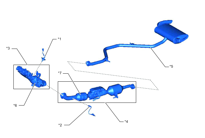
| *1 | Air Fuel Ratio Sensor (Sensor 1) | *2 | Heated Oxygen Sensor (Sensor 2) |
| *3 | Exhaust Manifold | *4 | Front Exhaust Pipe Assembly |
| *5 | Tail Exhaust Pipe Assembly | *6 | TWC: Front Catalyst |
| *7 | TWC: Rear Catalyst | - | - |
Note
When replacing the exhaust manifold (*3) and the front exhaust pipe assembly (*4) in order to replace the three-way catalytic converter, it is not necessary to replace the air fuel ratio sensor (*1) and the heated oxygen sensor (*2).
MONITOR STRATEGY
| Required Sensors/Components (Main) | Air fuel ratio sensor Heated oxygen sensor |
| Required Sensors/Components (Related) | Intake air temperature sensor Mass air flow meter sub-assembly Crankshaft position sensor Engine coolant temperature sensor |
| Frequency of Operation | Once per driving cycle |
TYPICAL ENABLING CONDITIONS
| Response rate during fuel cut from rich condition | Completed |
| Auxiliary battery voltage | 11 V or higher |
| Intake air temperature | -10°C (14°F) or higher |
| Engine coolant temperature | 75°C (167°F) or higher |
| Atmospheric pressure | 76 kPa(abs) [11 psi(abs)] or higher |
| Idling | Off |
| Engine speed | Less than 4500 rpm |
| Air fuel ratio sensor status | Activated |
| Fuel system status | Closed loop |
| Engine load | 10% or higher, and less than 80% |
| All of the following conditions are met | 1, 2 and 3 |
| 1. Mass air flow | 2.5 gm/sec or more, and less than 50 gm/sec |
| 2. Front catalyst temperature (estimated) | 450°C (842°F) or higher, and less than 770°C (1418°F) |
| 3. Rear catalyst temperature (estimated) | 330°C (626°F) or higher, and less than 700°C (1292°F) |
| Air fuel ratio imbalance of clogged EGR runner fail | Not set |
TYPICAL MALFUNCTION THRESHOLDS
| Oxygen Storage Capacity (OSC) of catalyst (Normalized) | Less than 1 |
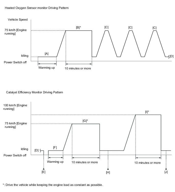
CONFIRMATION DRIVING PATTERN
Tech Tips
-
It is necessary for the response of the heated oxygen sensor to be normal in order to confirm DTC P042000. Therefore, perform the confirmation driving pattern for the heated oxygen sensor monitor before performing the confirmation driving pattern for the catalyst efficiency monitor.
-
Performing this confirmation driving pattern will activate the catalyst efficiency monitor. This is very useful for verifying the completion of a repair.
-
Connect the GTS to the DLC3.
-
Turn the power switch on (IG).
-
Turn the GTS on.
-
Clear the DTCs (even if no DTCs are stored, perform the clear DTC procedure).
-
Turn the power switch off and wait for at least 30 seconds.
-
Turn the power switch on (IG).
-
Turn the GTS on.
-
Put the engine in Inspection Mode (Maintenance Mode).
-
Start the engine and warm it up until the engine coolant temperature is 75°C (167°F) or higher with park (P) selected [A].
Tech Tips
In order to keep the idle stable, turn the A/C and all other electric loads off and do not perform any shift operations.
-
With the engine running, drive the vehicle at approximately 75 km/h (47 mph) for 10 minutes or more [B].
CAUTION:
When performing the confirmation driving pattern, obey all speed limits and traffic laws.
Tech Tips
-
Drive the vehicle while keeping the engine load as constant as possible.
-
If the engine stops, further depress the accelerator pedal to restart the engine.
-
-
With shift state B selected and the engine running, drive the vehicle at 75 km/h (47 mph), and then decelerate the vehicle by releasing the accelerator pedal for 5 seconds or more to perform the fuel-cut [C].
CAUTION:
When performing the confirmation driving pattern, obey all speed limits and traffic laws.
Tech Tips
If the engine stops, further depress the accelerator pedal to restart the engine.
-
Turn the power switch off and wait for at least 30 seconds [E].
-
Turn the power switch on (IG).
-
Turn the GTS on.
-
Start the engine and warm it up until the engine coolant temperature is 75°C (167°F) or higher [F].
-
With the engine running, drive the vehicle at approximately 75 km/h (47 mph) for 10 minutes or more [G].
CAUTION:
When performing the confirmation driving pattern, obey all speed limits and traffic laws.
Tech Tips
-
Drive the vehicle while keeping the engine load as constant as possible.
-
The monitor item will change to Complete as the Catalyst Efficiency monitor operates.
-
If the engine stops, further depress the accelerator pedal to restart the engine.
-
-
Enter the following menus: Powertrain / Engine / Trouble Codes [H].
-
Read the pending DTCs.
Tech Tips
-
If a pending DTC is output, the system is malfunctioning.
-
If a pending DTC is not output, perform the following procedure.
-
-
Enter the following menus: Powertrain / Engine / Utility / All Readiness.
-
Input the DTC: P042000.
-
Check the DTC judgment result.
GTS Display Description NORMAL
-
DTC judgment completed
-
System normal
ABNORMAL
-
DTC judgment completed
-
System abnormal
INCOMPLETE
-
DTC judgment not completed
-
Perform driving pattern after confirming DTC enabling conditions
N/A
-
Unable to perform DTC judgment
-
Number of DTCs which do not fulfill DTC preconditions has reached ECU memory limit
Tech Tips
-
If the judgment result is NORMAL, the system is normal.
-
If the judgment result is ABNORMAL, the system is malfunctioning.
-
If the judgment result is INCOMPLETE or N/A and no pending DTC is output, perform the following procedure.
-
-
Drive the vehicle at a speed between 75 and 100 km/h (47 and 63 mph) for 10 minutes or more [I].
CAUTION:
When performing the confirmation driving pattern, obey all speed limits and traffic laws.
Tech Tips
-
Drive the vehicle while keeping the engine load as constant as possible.
-
If the engine stops, further depress the accelerator pedal to restart the engine.
-
-
Enter the following menus: Powertrain / Engine / Trouble Codes [J].
-
Read the pending DTCs.
Tech Tips
-
If a pending DTC is output, the system is malfunctioning.
-
If a pending DTC is not output, perform the following procedure.
-
-
Enter the following menus: Powertrain / Engine / Utility / All Readiness.
-
Input the DTC: P042000.
-
Check the DTC judgment result.
GTS Display Description NORMAL
-
DTC judgment completed
-
System normal
ABNORMAL
-
DTC judgment completed
-
System abnormal
INCOMPLETE
-
DTC judgment not completed
-
Perform driving pattern after confirming DTC enabling conditions
N/A
-
Unable to perform DTC judgment
-
Number of DTCs which do not fulfill DTC preconditions has reached ECU memory limit
Tech Tips
-
If the judgment result is NORMAL, the system is normal.
-
If the judgment result is ABNORMAL, the system is malfunctioning.
-
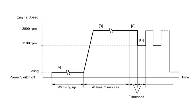
CONDITIONING FOR SENSOR TESTING
Tech Tips
Perform the operation with the engine speeds and time durations described below prior to checking the waveforms of the air fuel ratio and heated oxygen sensors. This is to activate the sensors sufficiently to obtain appropriate inspection results.
-
Connect the GTS to the DLC3.
-
Turn the power switch on (IG).
-
Turn the GTS on.
-
Put the engine in Inspection Mode (Maintenance Mode).
-
Start the engine and warm it up with the A/C switch and all accessories off until the engine coolant temperature stabilizes [A].
-
Enter the following menus: Powertrain / Engine / Data List / A/F (O2) Sensor Voltage B1S1 and O2 Sensor Voltage B1S2.
-
Run the engine at an engine speed of 2500 rpm for at least 3 minutes [B].
Tech Tips
During charge control, the engine speed is set at idle. Therefore, the engine speed will not increase when the accelerator pedal is depressed. In this case, perform step [B] after charge control has completed.
-
While running the engine at 2500 rpm and 1500 rpm for 2 seconds, check the waveform of the air fuel ratio sensor and heated oxygen sensor using the GTS [C].
Tech Tips
-
If the output voltage of either the air fuel ratio sensor or heated oxygen sensor does not fluctuate, or there is a noise in the waveform of either sensor, the sensor may be malfunctioning.
-
If the voltage outputs of both the sensors remain lean or rich, the air fuel ratio may be extremely lean or rich. In such a case, perform the Active Test "Control the Injection Volume for A/F Sensor" using the GTS.
-
If the Three-way Catalytic Converter (TWC) has deteriorated, the heated oxygen sensor (located behind the Three-way Catalytic Converter [TWC]) output voltage fluctuates up and down frequently, even under normal driving conditions (active air fuel ratio control is not performed).
CAUTION / NOTICE / HINT
Tech Tips
-
If a malfunction cannot be found when troubleshooting DTC P042000, a lean or rich abnormality may be the cause. Perform troubleshooting by following the inspection procedure for P017100 (System Too Lean) and P017200 (System Too Rich).
-
Sensor 1 refers to the sensor closest to the engine assembly.
-
Sensor 2 refers to the sensor farthest away from the engine assembly.
-
Read freeze frame data using the GTS. The ECM records vehicle and driving condition information as freeze frame data the moment a DTC is stored. When troubleshooting, freeze frame data can help determine if the vehicle was moving or stationary, if the engine was warmed up or not, if the air fuel ratio was lean or rich, and other data from the time the malfunction occurred.
PROCEDURE
-
CHECK ANY OTHER DTCS OUTPUT (IN ADDITION TO DTC P042000)
-
Connect the GTS to the DLC3.
-
Turn the power switch on (IG).
-
Turn the GTS on.
-
Enter the following menus: Powertrain / Engine / Trouble Codes.
-
Read the DTCs.
Powertrain > Engine > Trouble CodesResult Result Proceed to DTC P042000 is output A DTC P042000 and other DTCs are output B Tech Tips
If any DTCs other than P042000 are output, troubleshoot those DTCs first.
B 
GO TO DTC CHART Click here
A 
-
-
PERFORM ACTIVE TEST USING GTS (CONTROL THE INJECTION VOLUME FOR A/F SENSOR)
-
Connect the GTS to the DLC3.
-
Turn the power switch on (IG).
-
Turn the GTS on.
-
Put the engine in Inspection Mode (Maintenance Mode).
Powertrain > Hybrid Control > UtilityTester Display Inspection Mode -
Start the engine and warm it up until the engine coolant temperature is 75°C (167°F) or higher.
-
Idle the engine for 5 minutes or more with park (P) selected.
-
Enter the following menus: Powertrain / Engine / Active Test / Control the Injection Volume for A/F Sensor / Data List / Injection Volume, A/F (O2) Sensor Voltage B1S1 and O2 Sensor Voltage B1S2.
Powertrain > Engine > Active TestActive Test Display Control the Injection Volume for A/F Sensor Data List Display Injection Volume A/F (O2) Sensor Voltage B1S1 O2 Sensor Voltage B1S2 -
Change the fuel injection volume using the GTS, and monitor the output voltage of the air fuel ratio sensor (A/F (O2) Sensor Voltage B1S1) and heated oxygen sensor (O2 Sensor Voltage B1S2) displayed on the GTS.
Tech Tips
-
The Active Test "Control the Injection Volume for A/F Sensor" can be used to lower the fuel injection volume by 12.5% or increase the injection volume by 12.5%.
-
The air fuel ratio sensor is displayed as A/F (O2) Sensor Voltage B1S1, and the heated oxygen sensor is displayed as O2 Sensor Voltage B1S2 on the GTS.
-
The air fuel ratio sensor has an output delay of a few seconds and the heated oxygen sensor has a maximum output delay of approximately 20 seconds.
-
If the sensor output voltage does not change (almost no reaction) while performing the Active Test, the sensor may be malfunctioning.
Standard GTS Display
(Sensor)
Injection Volume Status Voltage A/F (O2) Sensor Voltage B1S1
(Air fuel ratio)
12.5% Rich Below 3.1 V -12.5% Lean Higher than 3.4 V O2 Sensor Voltage B1S2
(Heated oxygen)
12.5% Rich Higher than 0.55 V -12.5% Lean Below 0.4 V Result Status A/F (O2) Sensor Voltage B1S1 Status O2 Sensor Voltage B1S2 Actual air fuel ratio, air fuel ratio sensor and heated oxygen sensor condition Main Suspected Trouble Area Proceed to Lean/Rich Lean/Rich Normal
-
Three-way catalytic converter
-
Gas leak from exhaust system
-
EGR valve assembly
A Lean Lean/Rich Air fuel ratio sensor malfunction
-
Air fuel ratio sensor
B Rich Lean/Rich Air fuel ratio sensor malfunction
-
Air fuel ratio sensor
Lean/Rich Lean Heated oxygen sensor malfunction
-
Heated oxygen sensor
-
Gas leak from exhaust system
C Lean/Rich Rich Heated oxygen sensor malfunction
-
Heated oxygen sensor
-
Gas leak from exhaust system
Lean Lean Actual air fuel ratio lean
-
Extremely lean actual air fuel ratio
-
Gas leak from exhaust system
-
EGR valve assembly
D Rich Rich Actual air fuel ratio rich
-
Extremely rich actual air fuel ratio
-
Gas leak from exhaust system
-
EGR valve assembly
-
Lean: While performing the Active Test "Control the Injection Volume for A/F Sensor", the air fuel ratio sensor output voltage (A/F (O2) Sensor Voltage B1S1) is consistently higher than 3.4 V, and the heated oxygen sensor output voltage (O2 Sensor Voltage B1S2) is consistently below 0.4 V.
-
Rich: While performing the Active Test "Control the Injection Volume for A/F Sensor", the air fuel ratio sensor output voltage (A/F (O2) Sensor Voltage B1S1) is consistently below 3.1 V, and the heated oxygen sensor output voltage (O2 Sensor Voltage B1S2) is consistently higher than 0.55 V.
-
Lean/Rich: While performing the Active Test "Control the Injection Volume for A/F Sensor", the output voltage of the fuel ratio sensor (A/F (O2) Sensor Voltage B1S1) or heated oxygen sensor (O2 Sensor Voltage B1S2) alternates correctly.
-
B 
REPLACE AIR FUEL RATIO SENSOR Click here
C
CHECK FOR EXHAUST GAS LEAK Click here
D
CHECK FOR EXHAUST GAS LEAK Click here
A
-
-
CHECK FOR EXHAUST GAS LEAK
-
Check for exhaust gas leaks.
OK No gas leaks in exhaust system. Result Proceed to OK NG
NG
GO TO STEP 39 Click here
OK
-
-
PERFORM ACTIVE TEST USING GTS (CONTROL THE EGR STEP POSITION)
-
Connect the GTS to the DLC3.
-
Turn the power switch on (IG).
-
Turn the GTS on.
-
Put the engine in Inspection Mode (Maintenance Mode).
Powertrain > Hybrid Control > UtilityTester Display Inspection Mode -
Start the engine and warm it up until the engine coolant temperature is 75°C (167°F) or higher.
Tech Tips
The A/C switch and all accessories should be off.
-
Enter the following menus: Powertrain / Engine / Active Test / Control the EGR Step Position / Data List / Intake Manifold Absolute Pressure, EGR Step Position and Engine Independent.
Powertrain > Engine > Active TestActive Test Display Control the EGR Step Position Data List Display Intake Manifold Absolute Pressure EGR Step Position Engine Independent -
Confirm that the value of Data List item Engine Independent is "Operate" then check the value of Intake Manifold Absolute Pressure while performing the Active Test.
Note
-
Do not leave the EGR valve open for 10 seconds or more during the Active Test.
-
Be sure to return the EGR valve to step 0 when the Active Test is completed.
-
Do not open the EGR valve 30 steps or more during the Active Test.
OK The value of Intake Manifold Absolute Pressure changes in response to the EGR step position when the value of Engine Independent is "Operate". Standard - Control the EGR Step Position (Active Test) 0 Steps 0 to 30 Steps Intake Manifold Absolute Pressure
(Data List)
(EGR valve is fully closed) Intake Manifold Absolute Pressure value is at least +10 kPa (1.45 psi) higher than when EGR valve is fully closed Tech Tips
-
If the value of Data List item Engine Independent is "Not Opr" when the engine is idling, charge control is being performed. Perform the Active Test after charge control is complete ("Operate" is displayed).
-
While performing the Active Test, if the increase in the value of Intake Manifold Absolute Pressure is small, the EGR valve assembly may be malfunctioning.
-
Even if the EGR valve assembly is malfunctioning, rough idling or an increase in the value of Intake Manifold Absolute Pressure may occur while performing the Active Test. However, the amount that the value of Intake Manifold Absolute Pressure increases will be smaller than normal.
Result Result Proceed to The value of Intake Manifold Absolute Pressure increases by 10 kPa(abs) or more, compared to when the EGR valve was fully closed (0 step) OK Other than above NG Tech Tips
10 kPa = 1.45 psi
-
OK
GO TO STEP 42 Click here
NG
-
-
INSPECT EGR VALVE ASSEMBLY
-
Remove the EGR valve assembly.
Tech Tips
-
Check if the EGR valve is stuck open.
OK EGR valve is tightly closed. Result Proceed to OK NG
OK
GO TO STEP 42 Click here
NG
REPLACE EGR VALVE ASSEMBLY Click here Perform "Inspection After Repair" after replacing the EGR valve assembly. Click here
-
-
REPLACE AIR FUEL RATIO SENSOR
-
Replace the air fuel ratio sensor.
Tech Tips
-
Perform "Inspection After Repair" after replacing the air fuel ratio sensor.
Result Proceed to NEXT
NEXT
GO TO STEP 40 Click here
-
-
CHECK FOR EXHAUST GAS LEAK
-
Check for exhaust gas leaks.
OK No gas leaks in exhaust system. Result Proceed to OK NG
NG
GO TO STEP 39 Click here
OK
-
-
REPLACE HEATED OXYGEN SENSOR
-
Replace the heated oxygen sensor.
Tech Tips
-
Perform "Inspection After Repair" after replacing the heated oxygen sensor.
Result Proceed to NEXT
NEXT
GO TO STEP 40 Click here
-
-
CHECK FOR EXHAUST GAS LEAK
-
Check for exhaust gas leaks.
OK No gas leaks in exhaust system. Result Proceed to OK NG
NG
REPAIR OR REPLACE EXHAUST SYSTEM Click here
OK
-
-
PERFORM ACTIVE TEST USING GTS (CONTROL THE EGR STEP POSITION)
-
Connect the GTS to the DLC3.
-
Turn the power switch on (IG).
-
Turn the GTS on.
-
Put the engine in Inspection Mode (Maintenance Mode).
Powertrain > Hybrid Control > UtilityTester Display Inspection Mode -
Start the engine and warm it up until the engine coolant temperature is 75°C (167°F) or higher.
Tech Tips
The A/C switch and all accessories should be off.
-
Enter the following menus: Powertrain / Engine / Active Test / Control the EGR Step Position / Data List / Intake Manifold Absolute Pressure, EGR Step Position and Engine Independent.
Powertrain > Engine > Active TestActive Test Display Control the EGR Step Position Data List Display Intake Manifold Absolute Pressure EGR Step Position Engine Independent -
Confirm that the value of Data List item Engine Independent is "Operate" then check the value of Intake Manifold Absolute Pressure while performing the Active Test.
Note
-
Do not leave the EGR valve open for 10 seconds or more during the Active Test.
-
Be sure to return the EGR valve to step 0 when the Active Test is completed.
-
Do not open the EGR valve 30 steps or more during the Active Test.
OK The value of Intake Manifold Absolute Pressure changes in response to the EGR step position when the value of Engine Independent is "Operate". Standard - Control the EGR Step Position (Active Test) 0 Steps 0 to 30 Steps Intake Manifold Absolute Pressure
(Data List)
(EGR valve is fully closed) Intake Manifold Absolute Pressure value is at least +10 kPa (1.45 psi) higher than when EGR valve is fully closed Tech Tips
-
If the value of Data List item Engine Independent is "Not Opr" when the engine is idling, charge control is being performed. Perform the Active Test after charge control is complete ("Operate" is displayed).
-
While performing the Active Test, if the increase in the value of Intake Manifold Absolute Pressure is small, the EGR valve assembly may be malfunctioning.
-
Even if the EGR valve assembly is malfunctioning, rough idling or an increase in the value of Intake Manifold Absolute Pressure may occur while performing the Active Test. However, the amount that the value of Intake Manifold Absolute Pressure increases will be smaller than normal.
Result Result Proceed to The value of Intake Manifold Absolute Pressure increases by 10 kPa(abs) or more, compared to when the EGR valve was fully closed (0 step) OK Other than above NG Tech Tips
10 kPa = 1.45 psi
-
OK
GO TO STEP 12 Click here
NG
-
-
INSPECT EGR VALVE ASSEMBLY
-
Remove the EGR valve assembly.
Tech Tips
-
Check if the EGR valve is stuck open.
OK EGR valve is tightly closed. Result Proceed to OK NG
NG
REPLACE EGR VALVE ASSEMBLY Click here Perform "Inspection After Repair" after replacing the EGR valve assembly. Click here
OK
-
-
CHECK PCV HOSE CONNECTIONS
-
Check the PCV hose connections.
Tech Tips
OK PCV valve and hose are connected correctly and are not damaged. Result Proceed to OK NG
NG
REPAIR OR REPLACE PCV HOSE Click here
OK
-
-
CHECK INTAKE SYSTEM
-
Check the intake system for vacuum leaks.
OK No leaks from intake system. Result Proceed to OK NG
NG
REPAIR OR REPLACE INTAKE SYSTEM Click here
OK
-
-
PERFORM ACTIVE TEST USING GTS (CONTROL THE INJECTION VOLUME FOR A/F SENSOR)
-
Connect the GTS to the DLC3.
-
Turn the power switch on (IG).
-
Turn the GTS on.
-
Put the engine in Inspection Mode (Maintenance Mode).
Powertrain > Hybrid Control > UtilityTester Display Inspection Mode -
Start the engine and warm it up until the engine coolant temperature is 75°C (167°F) or higher.
-
Idle the engine for 5 minutes or more with park (P) selected.
-
Enter the following menus: Powertrain / Engine / Active Test / Control the Injection Volume for A/F Sensor / Data List / Injection Volume, A/F (O2) Sensor Voltage B1S1 and O2 Sensor Voltage B1S2.
Powertrain > Engine > Active TestActive Test Display Control the Injection Volume for A/F Sensor Data List Display Injection Volume A/F (O2) Sensor Voltage B1S1 O2 Sensor Voltage B1S2 -
Change the fuel injection volume using the GTS, and monitor the output voltage of the air fuel ratio sensor (A/F (O2) Sensor Voltage B1S1) and heated oxygen sensor (O2 Sensor Voltage B1S2) displayed on the GTS.
Tech Tips
-
The Active Test "Control the Injection Volume for A/F Sensor" can be used to lower the fuel injection volume by 12.5% or increase the injection volume by 12.5%.
-
The air fuel ratio sensor is displayed as A/F (O2) Sensor Voltage B1S1, and the heated oxygen sensor is displayed as O2 Sensor Voltage B1S2 on the GTS.
-
The air fuel ratio sensor has an output delay of a few seconds and the heated oxygen sensor has a maximum output delay of approximately 20 seconds.
-
If the sensor output voltage does not change (almost no reaction) while performing the Active Test, the sensor may be malfunctioning.
Standard GTS Display (Sensor) Injection Volume Status Voltage A/F (O2) Sensor Voltage B1S1
(Air fuel ratio)
12.5% Rich Below 3.1 V -12.5% Lean Higher than 3.4 V O2 Sensor Voltage B1S2
(Heated oxygen)
12.5% Rich Higher than 0.55 V -12.5% Lean Below 0.4 V Result Status A/F (O2) Sensor Voltage B1S1 Status O2 Sensor Voltage B1S2 Air Fuel Ratio Condition and Air Fuel Ratio Sensor Condition Suspected Trouble Area Proceed to Lean/Rich Lean/Rich Normal - A Lean Lean Actual air fuel ratio lean
-
PCV valve and hose
-
PCV hose connections
-
Fuel injector assembly blockage
-
Gas leak from exhaust system
-
Intake system
-
Fuel pressure
-
Mass air flow meter sub-assembly
-
Engine coolant temperature sensor
-
EGR valve assembly
Rich Rich Actual air fuel ratio rich
-
Fuel injector assembly leak or blockage
-
Gas leak from exhaust system
-
Ignition system
-
Fuel pressure
-
Mass air flow meter sub-assembly
-
Engine coolant temperature sensor
Lean Lean/Rich Air fuel ratio sensor malfunction
-
Air fuel ratio sensor
B Rich Lean/Rich Air fuel ratio sensor malfunction
-
Air fuel ratio sensor
-
Lean: While performing the Active Test "Control the Injection Volume for A/F Sensor", the air fuel ratio sensor output voltage (A/F (O2) Sensor Voltage B1S1) is consistently higher than 3.4 V, and the heated oxygen sensor output voltage (O2 Sensor Voltage B1S2) is consistently below 0.4 V.
-
Rich: While performing the Active Test "Control the Injection Volume for A/F Sensor", the air fuel ratio sensor output voltage (A/F (O2) Sensor Voltage B1S1) is consistently below 3.1 V, and the heated oxygen sensor output voltage (O2 Sensor Voltage B1S2) is consistently higher than 0.55 V.
-
Lean/Rich: While performing the Active Test "Control the Injection Volume for A/F Sensor", the output voltage of the fuel ratio sensor (A/F (O2) Sensor Voltage B1S1) or heated oxygen sensor (O2 Sensor Voltage B1S2) alternates correctly.
Tech Tips
Refer to "Data List / Active Test" [A/F (O2) Sensor Voltage B1S1 and O2 Sensor Voltage B1S2].
-
B
INSPECT AIR FUEL RATIO SENSOR (HEATER RESISTANCE) Click here
A
-
-
READ VALUE USING GTS (COOLANT TEMPERATURE)
-
Connect the GTS to the DLC3.
-
Turn the power switch on (IG).
-
Turn the GTS on.
-
Enter the following menus: Powertrain / Engine / Data List / Coolant Temperature.
Powertrain > Engine > Data ListTester Display Coolant Temperature -
Read the Data List twice, when the engine is both cold and warmed up.
Standard GTS Display Condition Specified Condition Coolant Temperature Cold engine Same as ambient air temperature Warm engine Between 75 and 100°C (167 and 212°F) Result Proceed to OK NG
NG
REPLACE ENGINE COOLANT TEMPERATURE SENSOR Click here
OK
-
-
PERFORM ACTIVE TEST USING GTS (CONTROL THE EGR STEP POSITION)
-
Connect the GTS to the DLC3.
-
Turn the power switch on (IG).
-
Turn the GTS on.
-
Put the engine in Inspection Mode (Maintenance Mode).
Powertrain > Hybrid Control > UtilityTester Display Inspection Mode -
Start the engine and warm it up until the engine coolant temperature is 75°C (167°F) or higher.
Tech Tips
The A/C switch and all accessories should be off.
-
Enter the following menus: Powertrain / Engine / Active Test / Control the EGR Step Position / Data List / Intake Manifold Absolute Pressure, EGR Step Position and Engine Independent.
Powertrain > Engine > Active TestActive Test Display Control the EGR Step Position Data List Display Intake Manifold Absolute Pressure EGR Step Position Engine Independent -
Confirm that the value of Data List item Engine Independent is "Operate" then check the value of Intake Manifold Absolute Pressure while performing the Active Test.
Note
-
Do not leave the EGR valve open for 10 seconds or more during the Active Test.
-
Be sure to return the EGR valve to step 0 when the Active Test is completed.
-
Do not open the EGR valve 30 steps or more during the Active Test.
OK The value of Intake Manifold Absolute Pressure changes in response to the EGR step position when the value of Engine Independent is "Operate". Standard - Control the EGR Step Position (Active Test) 0 Steps 0 to 30 Steps Intake Manifold Absolute Pressure
(Data List)
(EGR valve is fully closed) Intake Manifold Absolute Pressure value is at least +10 kPa (1.45 psi) higher than when EGR valve is fully closed Tech Tips
-
If the value of Data List item Engine Independent is "Not Opr" when the engine is idling, charge control is being performed. Perform the Active Test after charge control is complete ("Operate" is displayed).
-
While performing the Active Test, if the increase in the value of Intake Manifold Absolute Pressure is small, the EGR valve assembly may be malfunctioning.
-
Even if the EGR valve assembly is malfunctioning, rough idling or an increase in the value of Intake Manifold Absolute Pressure may occur while performing the Active Test. However, the amount that the value of Intake Manifold Absolute Pressure increases will be smaller than normal.
Result Result Proceed to The value of Intake Manifold Absolute Pressure increases by 10 kPa(abs) or more, compared to when the EGR valve was fully closed (0 step) OK Other than above NG Tech Tips
10 kPa = 1.45 psi
-
OK
GO TO STEP 18 Click here
NG
-
-
INSPECT EGR VALVE ASSEMBLY
-
Remove the EGR valve assembly.
Tech Tips
-
Check if the EGR valve is stuck open.
OK EGR valve is tightly closed. Result Proceed to OK NG
NG
REPLACE EGR VALVE ASSEMBLY Click here
OK
-
-
READ VALUE USING GTS (MASS AIR FLOW SENSOR)
-
Connect the GTS to the DLC3.
-
Turn the power switch on (IG).
-
Turn the GTS on.
-
Put the engine in Inspection Mode (Maintenance Mode).
Powertrain > Hybrid Control > UtilityTester Display Inspection Mode -
Start the engine.
-
Enter the following menus: Powertrain / Engine / Data List / Engine Speed, Mass Air Flow Sensor and Coolant Temperature.
Powertrain > Engine > Data ListTester Display Engine Speed Mass Air Flow Sensor Coolant Temperature -
Allow the engine to idle until Coolant Temperature is 75°C (167°F) or higher.
-
Read Mass Air Flow Sensor with the engine speed at 2500 rpm.
Tech Tips
During charge control, the engine speed is set at idle. Therefore, the engine speed will not increase when the accelerator pedal is depressed. In this case, read the Data List after charge control has completed.
Standard GTS Display Condition Specified Condition Mass Air Flow Sensor Engine warmed up
Shift position: P
A/C: Off
Engine Speed: 2500 rpm
Between 4.5 and 8.5 gm/sec Result Result Proceed to The value of Mass Air Flow Sensor is between 4.5 gm/sec and 8.5 gm/sec OK Other than above NG
NG
GO TO STEP 23 Click here
OK
-
-
CHECK FUEL PRESSURE
-
Check the fuel pressure.
Result Proceed to OK NG
NG
REPAIR OR REPLACE FUEL SYSTEM Click here
OK
-
-
CHECK FOR EXHAUST GAS LEAK
-
Check for exhaust gas leaks.
OK No gas leaks in exhaust system. Result Proceed to OK NG
NG
REPAIR OR REPLACE EXHAUST SYSTEM Click here
OK
-
-
INSPECT IGNITION SYSTEM
-
Inspect the ignition system.
Tech Tips
If the spark plugs or ignition system malfunctions, engine misfire may occur. The misfire count can be read using the GTS. Enter the following menus: Powertrain / Engine / Data List / Misfire Count Cylinder #1 to Misfire Count Cylinder #4.
Result Proceed to OK NG
NG
REPAIR OR REPLACE IGNITION SYSTEM Click here
OK
-
-
INSPECT FUEL INJECTOR ASSEMBLY (INJECTION AND VOLUME)
-
Check the injection and volume.
Tech Tips
-
Refer to the fuel injector assembly inspection procedure.
-
If the fuel injector assemblies malfunction, engine misfire may occur. The misfire count can be read using the GTS. Enter the following menus: Powertrain / Engine / Data List / Misfire Count Cylinder #1 to Misfire Count Cylinder #4.
Result Proceed to OK NG -
NG
REPLACE FUEL INJECTOR ASSEMBLY Click here
OK
-
-
CHECK HARNESS AND CONNECTOR (MASS AIR FLOW METER SUB-ASSEMBLY CONNECTOR CONNECTION)
-
Check the connection and terminal contact pressure of connectors and wire harnesses between the mass air flow meter sub-assembly and ECM.
Result Proceed to NEXT
NEXT
GO TO STEP 40 Click here
-
-
REPLACE FUEL INJECTOR ASSEMBLY
-
Replace the fuel injector assembly.
Tech Tips
-
Perform "Inspection After Repair" after replacing the fuel injector assembly.
Result Proceed to NEXT
NEXT
GO TO STEP 40 Click here
-
-
REPAIR OR REPLACE IGNITION SYSTEM
-
Repair or replace the ignition system.
Tech Tips
Perform "Inspection After Repair" after repairing or replacing the ignition system.
Result Proceed to NEXT
NEXT
GO TO STEP 40 Click here
-
-
REPAIR OR REPLACE EXHAUST SYSTEM
-
Repair or replace the exhaust system.
Tech Tips
Perform "Inspection After Repair" after repairing or replacing the exhaust system.
Result Proceed to NEXT
NEXT
GO TO STEP 40 Click here
-
-
REPAIR OR REPLACE FUEL SYSTEM
-
Repair or replace the fuel system.
Result Proceed to NEXT
NEXT
GO TO STEP 40 Click here
-
-
REPLACE EGR VALVE ASSEMBLY
-
Replace the EGR valve assembly.
Tech Tips
-
Perform "Inspection After Repair" after replacing the EGR valve assembly.
Result Proceed to NEXT
NEXT
GO TO STEP 40 Click here
-
-
REPLACE ENGINE COOLANT TEMPERATURE SENSOR
-
Replace the engine coolant temperature sensor.
Tech Tips
-
Perform "Inspection After Repair" after replacing the engine coolant temperature sensor.
Result Proceed to NEXT
NEXT
GO TO STEP 40 Click here
-
-
INSPECT AIR FUEL RATIO SENSOR (HEATER RESISTANCE)
-
Inspect the air fuel ratio sensor.
Result Proceed to OK NG
NG
REPLACE AIR FUEL RATIO SENSOR Click here
OK
-
-
CHECK TERMINAL VOLTAGE (POWER SOURCE OF AIR FUEL RATIO SENSOR)
-
Disconnect the air fuel ratio sensor connector.
-
Turn the power switch on (IG).
-
Measure the voltage according to the value(s) in the table below.
Standard Voltage Tester Connection Condition Specified Condition C24-2 (+B) - Body ground Power switch on (IG) 11 to 14 V Result Proceed to OK NG
NG
REPAIR OR REPLACE HARNESS OR CONNECTOR (NO. 1 INTEGRATION RELAY - AIR FUEL RATIO SENSOR) Click here
OK
-
-
CHECK HARNESS AND CONNECTOR (AIR FUEL RATIO SENSOR - ECM)
-
Disconnect the air fuel ratio sensor connector.
-
Disconnect the ECM connector.
-
Measure the resistance according to the value(s) in the table below.
Standard Resistance Tester Connection Condition Specified Condition C24-1 (HA1A) - C31-27 (HA1A) Always Below 1 Ω C24-3 (A1A+) - C31-100 (A1A+) Always Below 1 Ω C24-4 (A1A-) - C31-132 (A1A-) Always Below 1 Ω C24-1 (HA1A) or C31-27 (HA1A) - Body ground and other terminals Always 10 kΩ or higher C24-3 (A1A+) or C31-100 (A1A+) - Body ground and other terminals Always 10 kΩ or higher C24-4 (A1A-) or C31-132 (A1A-) - Body ground and other terminals Always 10 kΩ or higher Result Proceed to OK NG
NG
REPAIR OR REPLACE HARNESS OR CONNECTOR Click here
OK
-
-
REPLACE AIR FUEL RATIO SENSOR
-
Replace the air fuel ratio sensor.
Tech Tips
-
Perform "Inspection After Repair" after replacing the air fuel ratio sensor.
Result Proceed to NEXT
NEXT
GO TO STEP 40 Click here
-
-
REPAIR OR REPLACE HARNESS OR CONNECTOR
-
Repair or replace the wire harness or connector.
Result Proceed to NEXT
NEXT
GO TO STEP 40 Click here
-
-
REPAIR OR REPLACE HARNESS OR CONNECTOR (NO. 1 INTEGRATION RELAY - AIR FUEL RATIO SENSOR)
-
Repair or replace the wire harness or connector.
Result Proceed to NEXT
NEXT
GO TO STEP 40 Click here
-
-
REPLACE AIR FUEL RATIO SENSOR
-
Replace the air fuel ratio sensor.
Tech Tips
-
Perform "Inspection After Repair" after replacing the air fuel ratio sensor.
Result Proceed to NEXT
NEXT
GO TO STEP 40 Click here
-
-
REPAIR OR REPLACE INTAKE SYSTEM
-
Repair or replace the intake system.
Tech Tips
Perform "Inspection After Repair" after repairing or replacing the intake system.
Result Proceed to NEXT
NEXT
GO TO STEP 40 Click here
-
-
REPAIR OR REPLACE PCV HOSE
-
Repair or replace the PCV hose.
Result Proceed to NEXT
NEXT
GO TO STEP 40 Click here
-
-
REPAIR OR REPLACE EXHAUST SYSTEM
-
Repair or replace exhaust system.
Tech Tips
Perform "Inspection After Repair" after repairing or replacing the exhaust system.
Result Proceed to NEXT
NEXT
-
-
CLEAR DTC
-
Connect the GTS to the DLC3.
-
Turn the power switch on (IG).
-
Turn the GTS on.
-
Clear the DTCs.
Powertrain > Engine > Clear DTCs -
Turn the power switch off and wait for at least 30 seconds.
Result Proceed to NEXT
NEXT
-
-
CONFIRM WHETHER MALFUNCTION HAS BEEN SUCCESSFULLY REPAIRED
-
Drive the vehicle in accordance with the driving pattern described in Confirmation Driving Pattern.
-
Enter the following menus: Powertrain / Engine / Trouble Codes.
-
Read the DTCs.
Powertrain > Engine > Trouble CodesResult Result Proceed to DTCs are not output A P042000 is output B
A
END
B
-
-
REPLACE EXHAUST MANIFOLD (TWC: FRONT CATALYST) AND FRONT EXHAUST PIPE ASSEMBLY (TWC: REAR CATALYST)
Note
When replacing the exhaust manifold and front exhaust pipe assembly in order to replace the three-way catalytic converter, it is not necessary to replace the air fuel ratio sensor and the heated oxygen sensor.
Tech Tips
Confirm the replacement parts, referring to the illustration in the Catalyst Location.
-
Replace the exhaust manifold (TWC: Front catalyst).
Tech Tips
-
Replace the front exhaust pipe assembly (TWC: Rear catalyst).
Tech Tips
Result Proceed to NEXT
NEXT
END
-