DYNAMIC RADAR CRUISE CONTROL SYSTEM TERMINALS OF ECU
-
CHECK HYBRID VEHICLE CONTROL ECU
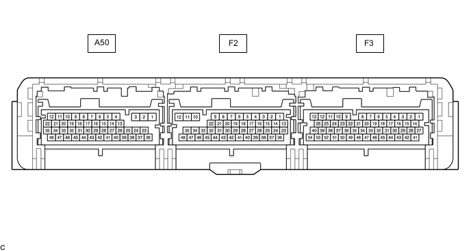
Terminal No. (Symbols) Wiring Color Terminal Description Condition Specified Condition A50-7 (STP) - F3-3 (E1) SB - BR Stop light switch assembly signal Brake pedal depressed 11 to 14 V A50-7 (STP) - F3-3 (E1) SB - BR Stop light switch assembly signal Brake pedal released Below 1 V F3-52 (VSI1) - F3-51 (E2X1) BR - GR Shift sensor (Main) Power switch on (IG), shift lever in home position or N 2.0 to 3.0 V F3-52 (VSI1) - F3-51 (E2X1) BR - GR Shift sensor (Main) Power switch on (IG), shift lever in R 0.3 to 1.8 V F3-52 (VSI1) - F3-51 (E2X1) BR - GR Shift sensor (Main) Power switch on (IG), shift lever in B or D 3.2 to 4.8 V F3-50 (VSI2) - F3-49 (E2X2) R - BE Shift sensor (Sub) Power switch on (IG), shift lever in home position or N 2.0 to 3.0 V F3-50 (VSI2) - F3-49 (E2X2) R - BE Shift sensor (Sub) Power switch on (IG), shift lever in R 0.3 to 1.8 V F3-50 (VSI2) - F3-49 (E2X2) R - BE Shift sensor (Sub) Power switch on (IG), shift lever in B or D 3.2 to 4.8 V F2-28 (ST1-) - F3-3 (E1) P - BR Stop light switch assembly signal Power switch on (IG), brake pedal depressed Below 1 V F2-28 (ST1-) - F3-3 (E1) P - BR Stop light switch assembly signal Power switch on (IG), brake pedal released 11 to 14 V F3-14 (CCS) - F3-3 (E1) BE - BR Cruise control main switch circuit Cruise control main switch (ON/OFF button) not pushed 1 MΩ or higher F3-14 (CCS) - F3-3 (E1) BE - BR Cruise control main switch circuit Cruise control main switch (ON/OFF button) pushed Below 2.5 Ω F3-14 (CCS) - F3-3 (E1) BE - BR Cruise control main switch circuit +RES switch ON 235 to 245 Ω F3-14 (CCS) - F3-3 (E1) BE - BR Cruise control main switch circuit -SET switch ON 617 to 643 Ω F3-14 (CCS) - F3-3 (E1) BE - BR Cruise control main switch circuit CANCEL switch ON 1509 to 1571 Ω F3-27 (BATT) - F3-3 (E1) GR - BR Constant power source Always 11 to 14 V -
CHECK DRIVING SUPPORT ECU ASSEMBLY

Note
Do not apply excessive force to the connector. If a force of 10 kg or more is applied, the connector may be broken.
Terminal No. (Symbol) Wiring Color Terminal Description Condition Specified Condition F40-3 (BZ) - F40-28 (GND) P - W-B Skid control buzzer assembly output Power switch on (IG), buzzer not sounding 11 to 14 V Power switch on (IG), buzzer sounding Below 1 V F40-7 (B) - F40-28 (GND) P*1 - W-B
B*2 - W-B
Power source Power switch on (IG) 11 to 14 V Power switch off Below 1 V F40-8 (CA1P) - F40-28 (GND) LG - W-B CAN communication signal Power switch on (IG) Pulse generation
(See waveform 1)
F40-9 (CA1N) - F40-28 (GND) W - W-B CAN communication signal Power switch on (IG) Pulse generation
(See waveform 2)
F40-10 (CA2H) - F40-28 (GND) G - W-B CAN communication signal Power switch on (IG) Pulse generation
(See waveform 1)
F40-11 (CA2L) - F40-28 (GND) W - W-B CAN communication signal Power switch on (IG) Pulse generation
(See waveform 2)
F40-23 (SPSW) - F40-28 (GND) GR - W-B Steering pad switch assembly signal (distance control signal) Power switch on (IG), steering pad switch assembly (distance control switch) off 4.75 to 5.25 V Power switch on (IG), steering pad switch assembly (distance control switch) on Below 1 V F40-28 (GND) - Body ground W-B - Body ground Ground Always Below 1 Ω *1: LHD
*2: RHD
-
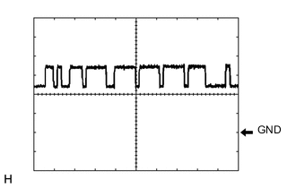
Waveform 1
-
CAN communication signal
Item Content Tester Connection
-
Between F40-8 (CA1P) and F40-28 (GND)
-
Between F40-10 (CA2H) and F40-28 (GND)
Tool Setting 1 V/DIV., 10 μsec./DIV. Condition Power switch on (IG) Tech Tips
The waveform varies depending on the CAN communication signal.
-
-
-
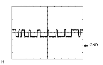
Waveform 2
-
CAN communication signal
Item Content Tester Connection
-
Between F40-9 (CA1N) and F40-28 (GND)
-
Between F40-11 (CA2L) and F40-28 (GND)
Tool Setting 1 V/DIV., 10 μsec./DIV. Condition Power switch on (IG) Tech Tips
The waveform varies depending on the CAN communication signal.
-
-
-
-
CHECK MILLIMETER WAVE RADAR SENSOR

Terminal No. (Symbol) Wiring Color Terminal Description Condition Specified Condition A2-1 (SGND) - Body ground W-B - Body ground Ground Always Below 1 Ω A2-2 (CA2L) - A2-1 (SGND) W - W-B CAN communication signal Power switch on (IG) Pulse generation
(See waveform 2)
A2-3 (CA2H) - A2-1 (SGND) G - W-B CAN communication signal Power switch on (IG) Pulse generation
(See waveform 1)
A2-5 (CA1P) - A2-1 (SGND) B - W-B CAN communication signal Power switch on (IG) Pulse generation
(See waveform 1)
A2-6 (CA1N) - A2-1 (SGND) W - W-B CAN communication signal Power switch on (IG) Pulse generation
(See waveform 2)
A2-8 (IGB) - A2-1 (SGND) LG - W-B Power source Power switch on (IG) 11 to 14 V
-
Waveform 1
-
CAN communication signal
Item Content Tester Connection
-
Between A2-3 (CA2H) and A2-1 (SGND)
-
Between A2-5 (CA1P) and A2-1 (SGND)
Tool Setting 1 V/DIV., 10 μsec./DIV. Condition Power switch on (IG) Tech Tips
The waveform varies depending on the CAN communication signal.
-
-
-
Waveform 2
-
CAN communication signal
Item Content Tester Connection
-
Between A2-2 (CA2L) and A2-1 (SGND)
-
Between A2-6 (CA1N) and A2-1 (SGND)
Tool Setting 1 V/DIV., 10 μsec./DIV. Condition Power switch on (IG) Tech Tips
The waveform varies depending on the CAN communication signal.
-
-
-