CRUISE CONTROL SYSTEM TERMINALS OF ECU
-
CHECK HYBRID VEHICLE CONTROL ECU
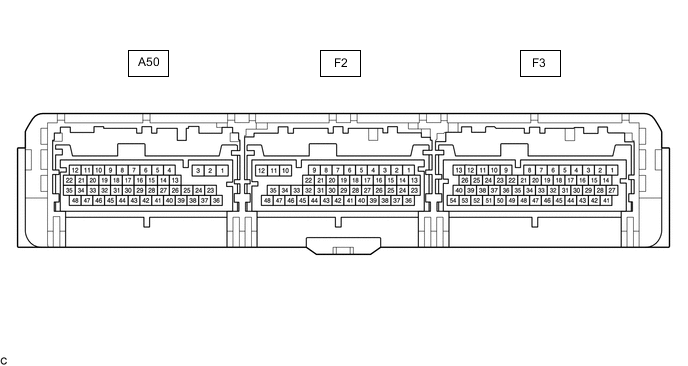
Terminal No. (Symbols) Wiring Color Terminal Description Condition Specified Condition A50-7 (STP) - F3-3 (E1) SB - W-B Stop light switch assembly signal Brake pedal depressed 11 to 14 V A50-7 (STP) - F3-3 (E1) SB - W-B Stop light switch assembly signal Brake pedal released Below 1 V F3-52 (VSI1) - F3-51 (E2X1) BR - GR Shift sensor (Main) Power switch on (IG), shift lever in home position or N 2.0 to 3.0 V F3-52 (VSI1) - F3-51 (E2X1) BR - GR Shift sensor (Main) Power switch on (IG), shift lever in R 0.3 to 1.8 V F3-52 (VSI1) - F3-51 (E2X1) BR - GR Shift sensor (Main) Power switch on (IG), shift lever in B or D 3.2 to 4.8 V F3-50 (VSI2) - F3-49 (E2X2) R - BE Shift sensor (Sub) Power switch on (IG), shift lever in home position or N 2.0 to 3.0 V F3-50 (VSI2) - F3-49 (E2X2) R - BE Shift sensor (Sub) Power switch on (IG), shift lever in R 0.3 to 1.8 V F3-50 (VSI2) - F3-49 (E2X2) R - BE Shift sensor (Sub) Power switch on (IG), shift lever in B or D 3.2 to 4.8 V F2-28 (ST1-) - F3-3 (E1) P - W-B Stop light switch assembly signal Power switch on (IG), Brake pedal depressed Below 1 V F2-28 (ST1-) - F3-3 (E1) P - W-B Stop light switch assembly signal Power switch on (IG), Brake pedal released 11 to 14 V F3-14 (CCS) - F3-3 (E1) BE - W-B Cruise control main switch circuit Cruise control main switch (ON-OFF button) not pushed 1 MΩ or higher F3-14 (CCS) - F3-3 (E1) BE - W-B Cruise control main switch circuit Cruise control main switch (ON-OFF button) pushed Below 2.5 Ω F3-14 (CCS) - F3-3 (E1) BE - W-B Cruise control main switch circuit +RES switch ON 235 to 245 Ω F3-14 (CCS) - F3-3 (E1) BE - W-B Cruise control main switch circuit -SET switch ON 617 to 643 Ω F3-14 (CCS) - F3-3 (E1) BE - W-B Cruise control main switch circuit CANCEL switch ON 1509 to 1571 Ω F3-27 (BATT) - F3-3 (E1) GR - W-B Constant power source Always 11 to 14 V