OIL PUMP REMOVAL
CAUTION / NOTICE / HINT
The necessary procedures (adjustment, calibration, initialization, or registration) that must be performed after parts are removed, installed, or replaced during the oil pump removal/installation are shown below.
| Replaced Part or Performed Procedure | Necessary Procedure | Effect/Inoperative Function when Necessary Procedure not Performed | Link |
|---|---|---|---|
| Auxiliary battery terminal is disconnected/reconnected | Memorize steering angle neutral point | Lane departure alert system (w/ Steering Control) | |
| Intelligent clearance sonar system*1 | |||
| Simple intelligent parking assist system*1 | |||
| Pre-crash safety system | |||
| Parking assist monitor system | |||
| Initialize back door lock | Power door lock control system | ||
| Replacement of inverter with converter assembly | Resolver learning |
|
|
for SFI system (w/ Canister Pump Module) |
Perform Vehicle Identification Number (VIN) registration | MIL comes on | |
for SFI system (w/o Canister Pump Module) |
Perform Vehicle Identification Number (VIN) or frame number registration | ||
for SFI system (w/ Canister Pump Module) |
Inspection After Repair |
|
|
for SFI system (w/o Canister Pump Module) |
Inspection After Repair |
|
|
| Suspension, tires, etc. (The vehicle height changes because of suspension or tire replacement) |
|
|
|
| Rear television camera assembly optical axis (Back camera position setting) | Parking assist monitor system | ||
| Initialize No. 1 headlight ECU sub-assembly LH | Automatic headlight beam level control system | ||
| Front wheel alignment adjustment |
|
|
|
| Replacement of hybrid vehicle transaxle assembly |
|
|
*1: When performing learning using the GTS.
PROCEDURE
-
REMOVE CHAIN SUB-ASSEMBLY
-
REMOVE CRANKSHAFT TIMING SPROCKET
-
REMOVE NO. 2 CHAIN SUB-ASSEMBLY
-
REMOVE NO. 2 OIL PAN SUB-ASSEMBLY
-
REMOVE OIL PUMP ASSEMBLY
-
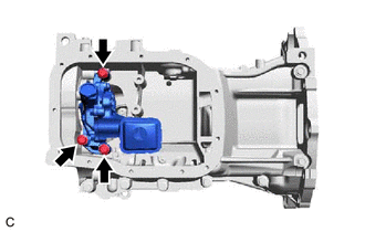
Remove the 3 bolts and oil pump assembly from the stiffening crankcase assembly.
-