BLACK OUT TAPE(for Rear Door) INSTALLATION
CAUTION / NOTICE / HINT
Tech Tips
-
Use the same procedure for the RH and LH sides.
-
The procedure listed below is for the LH side.
PROCEDURE
-
REPAIR INSTRUCTION
-
INSTALL NO. 3 BLACK OUT TAPE LH
Tech Tips
When installing the No. 3 black out tape LH, heat the front door panel and No. 3 black out tape LH using a heat light.
Standard Item Temperature Front Door Panel 40 to 60°C (104 to 140°F) No. 3 Black Out Tape LH 20 to 30°C (68 to 86°F) Note
Do not heat the front door panel or No. 3 black out tape LH excessively.
-
Refer to the illustration to position a new No. 3 black out tape LH.
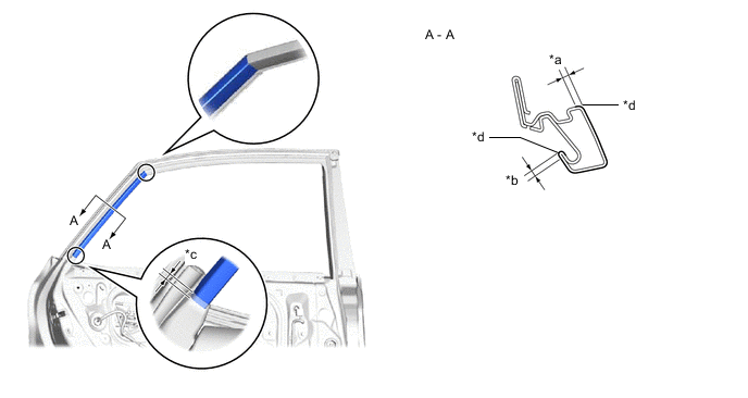
*a 1.5 mm (0.0591 in.) *b 1.0 mm (0.0394 in.) *c 5.0 mm (0.197 in.) *d Edge of Curved Surface -
Remove the release paper from the No. 3 black out tape LH.
-
-
INSTALL NO. 2 BLACK OUT TAPE LH
Tech Tips
When installing the No. 2 black out tape LH, heat the front door panel and No. 2 black out tape LH using a heat light.
Standard Item Temperature Front Door Panel 40 to 60°C (104 to 140°F) No. 2 Black Out Tape LH 20 to 30°C (68 to 86°F) Note
Do not heat the front door panel or No. 2 black out tape LH excessively.
-
Refer to the illustration to position a new No. 2 black out tape LH.
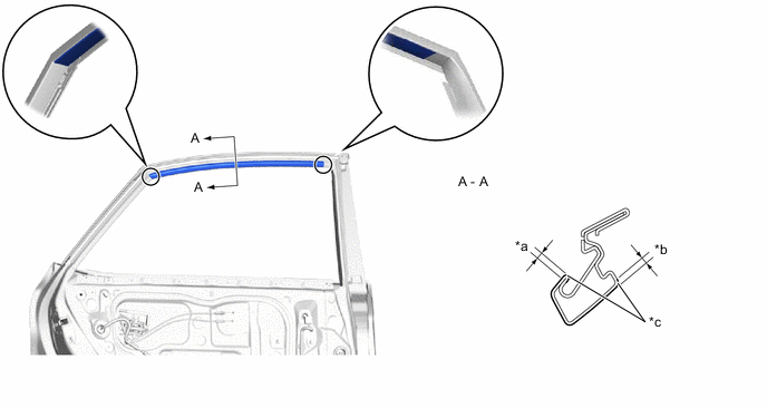
*a 1.5 mm (0.0591 in.) *b 1.0 mm (0.0394 in.) *c Edge of Curved Surface - - -
Remove the release paper from the No. 2 black out tape LH.
-
-
INSTALL NO. 1 BLACK OUT TAPE LH
Tech Tips
When installing the No. 1 black out tape LH, heat the front door panel and No. 1 black out tape LH using a heat light.
Standard Item Temperature Front Door Panel 40 to 60°C (104 to 140°F) No. 1 Black Out Tape LH 20 to 30°C (68 to 86°F) Note
Do not heat the front door panel or No. 1 black out tape LH excessively.
-
Refer to the illustration to position a new No. 1 black out tape LH.
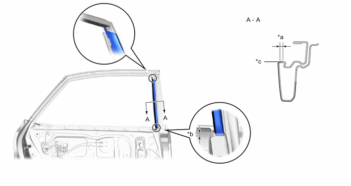
*a 1.0 mm (0.0394 in.) *b 5.0 mm (0.197 in.) *c Edge of Curved Surface - - -
Remove the release paper from the No. 1 black out tape LH.
-
-
INSTALL REAR DOOR REAR WINDOW FRAME MOULDING LH
-
INSTALL REAR DOOR UPPER WINDOW FRAME MOULDING LH
-
INSTALL REAR DOOR FRONT WINDOW FRAME MOULDING LH
-
INSTALL REAR DOOR BELT MOULDING ASSEMBLY LH
-
INSTALL REAR DOOR FRAME GARNISH LH
-
INSTALL REAR DOOR WEATHERSTRIP LH
-
CONNECT REAR DOOR CHECK ASSEMBLY LH
-
Apply MP grease to the sliding area of the rear door check assembly LH.
-
When reusing a bolt:
-
Clean the threads of the bolt with non-residue solvent.
-
Apply adhesive to the threads of the bolt.
Adhesive Toyota Genuine Adhesive 1324, Three Bond 1324 or equivalent.
-
-
Connect the rear door check assembly LH with the bolt.
- Torque:
- 27 N*m { 275 kgf*cm, 20 ft.*lbf }
-
-
INSTALL REAR DOOR GLASS SUB-ASSEMBLY LH
-
INSTALL REAR DOOR REAR GUIDE SEAL LH
-
INSTALL REAR DOOR REAR LOWER WINDOW FRAME SUB-ASSEMBLY LH
-
INSTALL REAR DOOR GLASS RUN LH
-
INSTALL REAR DOOR SERVICE HOLE COVER LH
-
INSTALL REAR DOOR ARMREST SET BRACKET LH
-
INSTALL REAR DOOR INNER GLASS WEATHERSTRIP LH
-
INSTALL REAR DOOR TRIM BOARD SUB-ASSEMBLY LH
-
INSTALL REAR POWER WINDOW REGULATOR SWITCH ASSEMBLY WITH REAR DOOR ARMREST BASE PANEL
-
INSTALL REAR DOOR INSIDE HANDLE BEZEL PLUG LH
-
INSTALL REAR DOOR TRIM COVER LH
-
CONNECT CABLE TO NEGATIVE AUXILIARY BATTERY TERMINAL
-
INSTALL DECK FLOOR BOX LH (w/ Spare Tire)
-
INSTALL REAR DECK FLOOR BOX (w/ Spare Tire)
-
INSTALL NO. 3 DECK BOARD SUB-ASSEMBLY (w/ Spare Tire)
-
INITIALIZE POWER WINDOW CONTROL SYSTEM
-
CHECK POWER WINDOW CONTROL SYSTEM