VEHICLE PROXIMITY NOTIFICATION SYSTEM Communication between Vehicle Proximity Notification System and Diagnostic Tool is not Possible
DESCRIPTION
The vehicle approaching speaker controller communicates with the GTS through the DLC3.
WIRING DIAGRAM
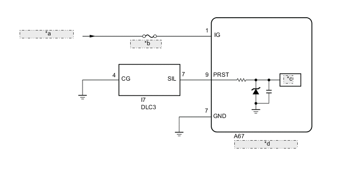
| *a | from IG1 NO.1 Relay |
| *b | ECU-IG NO.3 |
| *c | MPU |
| *d | Vehicle Approaching Speaker Controller |
CAUTION / NOTICE / HINT
Note
Inspect the fuses for circuits related to this system before performing the following procedure.
PROCEDURE
-
CHECK CHECK FOR
-
Connect the GTS to the DLC3.
-
Turn the power switch on (IG).
-
Turn the GTS on.
-
Enter the following menus: Health Check.
CAN Bus CheckOK Vehicle approaching speaker controller can communicate with the GTS. Result Proceed to OK NG
OK 
USE SIMULATION METHOD TO CHECK Click here
NG 
-
-
CHECK HARNESS AND CONNECTOR (VEHICLE APPROACHING SPEAKER CONTROLLER - BATTERY AND BODY GROUND)
-
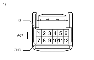
*a Front view of wire harness connector
(to Vehicle Approaching Speaker Controller)
Disconnect the vehicle approaching speaker controller connector.
-
Measure the voltage according to the value(s) in the table below.
Standard Voltage Tester Connection Switch Condition Specified Condition A67-1 (IG) - Body ground Power switch on (IG) 11 to 14 V -
Measure the resistance according to the value(s) in the table below.
Standard Resistance Tester Connection Condition Specified Condition A67-7 (GND) - Body ground Always Below 1 Ω Result Result OK NG
NG
REPAIR OR REPLACE HARNESS OR CONNECTOR
OK
-
-
CHECK HARNESS AND CONNECTOR (VEHICLE APPROACHING SPEAKER CONTROLLER - DLC3)
-
Disconnect the A67 vehicle approaching speaker controller connector.
-
Measure the resistance according to the value(s) in the table below.
Standard Resistance Tester Connection Condition Specified Condition A67-9 (PRST) - I7-7 (SIL) Always Below 1 Ω A67-9 (PRST) or I7-7 (SIL) - Body ground Always 10 kΩ or higher Result Result OK NG
NG
REPAIR OR REPLACE HARNESS OR CONNECTOR
OK
-
-
CHECK HARNESS AND CONNECTOR (DLC3 - BODY GROUND)
-
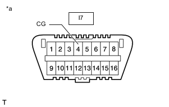
*a Front view of DLC3 Measure the resistance according to the value(s) in the table below.
Standard Resistance Tester Connection Condition Specified Condition I7-4 (CG) - Body ground Always Below 1 Ω Result Result OK NG
OK
REPLACE VEHICLE APPROACHING SPEAKER CONTROLLER Click here
NG
REPAIR OR REPLACE HARNESS OR CONNECTOR
-