VEHICLE PROXIMITY NOTIFICATION SYSTEM Vehicle Approaching Speaker Switch Indicator does not Illuminate or Turn OFF
DESCRIPTION
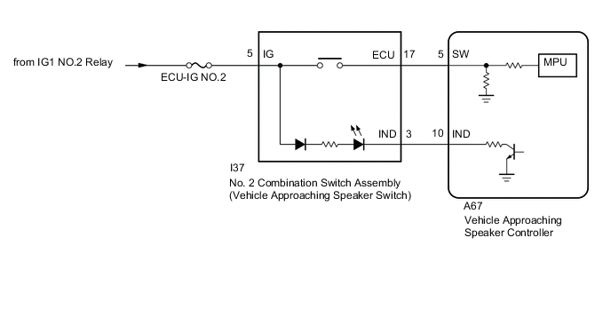
When the No. 2 combination switch assembly (vehicle approaching speaker switch) is turned on (sound stopped), the vehicle approaching speaker controller receives a proximity sound pause signal and illuminates the No. 2 combination switch assembly (vehicle approaching speaker switch) indicator.
WIRING DIAGRAM
CAUTION / NOTICE / HINT
Note
Inspect the fuses for circuits related to this system before performing the following procedure.
PROCEDURE
-
READ VALUE USING GTS (Operation Cancel SW)
-
Using the GTS, read the Data List.
Body Electrical > Vehicle Proximity Notification System > Data ListTester Display Measurement Item Normal Condition Reference Value Diagnostic Note Operation Cancel SW Vehicle approaching speaker switch signal OFF or ON OFF: Vehicle approaching speaker switch off
ON: Vehicle approaching speaker switch on
-
Body Electrical > Vehicle Proximity Notification System > Data ListTester Display Operation Cancel SW OK The GTS display changes according to the vehicle approaching speaker switch operation. Result Proceed to OK NG
NG 
GO TO OTHER DIAGNOSIS PROCEDURE (Sound does not Turn ON or OFF when the Vehicle Approaching Speaker Switch is Pressed) Click here
OK 
-
-
INSPECT NO. 2 COMBINATION SWITCH ASSEMBLY (VEHICLE APPROACHING SPEAKER SWITCH)
-
Remove the No. 2 combination switch assembly (vehicle approaching speaker switch).
-
Inspect the No. 2 combination switch assembly (vehicle approaching speaker switch).
Result Proceed to OK NG
NG
REPLACE NO. 2 COMBINATION SWITCH ASSEMBLY (VEHICLE APPROACHING SPEAKER SWITCH) Click here
OK
-
-
CHECK HARNESS AND CONNECTOR (VEHICLE APPROACHING SPEAKER CONTROLLER - NO. 2 COMBINATION SWITCH ASSEMBLY [VEHICLE APPROACHING SPEAKER SWITCH])
-
Disconnect the A67 vehicle approaching speaker controller connector.
-
Disconnect the I37 No. 2 combination switch assembly (vehicle approaching speaker switch) connector.
-
Measure the resistance according to the value(s) in the table below.
Standard Resistance Tester Connection Condition Specified Condition A67-10 (IND) - I37-3 (IND) Always Below 1 Ω A67-10 (IND) or I37-3 (IND) - Body ground Always 10 kΩ or higher Result Proceed to OK NG
OK
REPLACE VEHICLE APPROACHING SPEAKER CONTROLLER Click here
NG
REPAIR OR REPLACE HARNESS OR CONNECTOR
-