VEHICLE PROXIMITY NOTIFICATION SYSTEM There is No Sound Made
DESCRIPTION
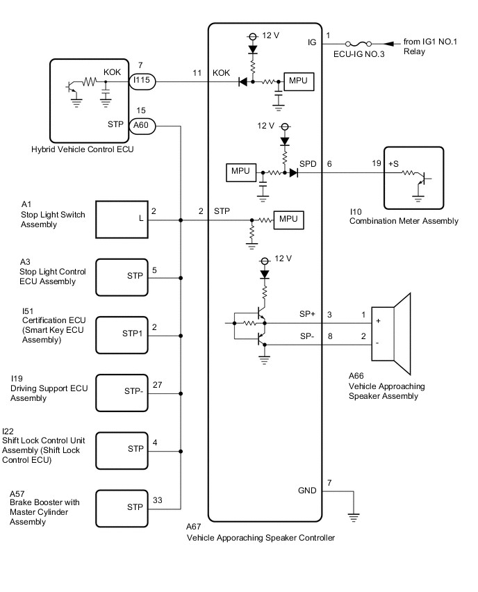
The vehicle approaching speaker controller receives stop light switch signals from the stop light switch assembly, vehicle speed signals from the combination meter assembly and "permission signals*" from the hybrid vehicle control ECU, and produces the warning sound from the vehicle approaching speaker assembly.
*: Permission signals
Tech Tips
-
Vehicle proximity notification system operation permitted (engine is stopped and shift lever is not in P).
-
Vehicle proximity notification system operation prohibited (engine is operating or shift lever is in P).
WIRING DIAGRAM
CAUTION / NOTICE / HINT
Note
-
Inspect the fuses for circuits related to this system before performing the following procedure.
-
Make sure that the vehicle approaching speaker switch is not pressed.
PROCEDURE
-
CHECK FOR DTC
-
Check for DTCs.
Body Electrical > Vehicle Proximity Notification System > Trouble CodesOK DTCs are not output. Result Result Proceed to DTC B1350 is not output. A DTC B1350 is output. B Communication with the GTS is not possible. C
B 
GO TO DTC CHART B1350 Click here
C
GO TO OTHER DIAGNOSIS PROCEDURE (Communication between Vehicle Proximity Notification System and Diagnostic Tool is not Possible) Click here
A 
-
-
PERFORM ACTIVE TEST USING GTS (Proximity Sound [Vehicle Stationary])
-
Using the GTS, perform the Active Test.
Body Electrical > Vehicle Proximity Notification System > Active TestTester Display Measurement Item Control Range Diagnostic Note Proximity Sound (Vehicle Stationary) Proximity sound (Vehicle stationary) OFF or ON Produces warning sound when vehicle is stopped
Body Electrical > Vehicle Proximity Notification System > Active TestTester Display Proximity Sound (Vehicle Stationary) OK The vehicle proximity notification system sounds or stops sounding according to the GTS display. Result Proceed to OK NG
NG 
CHECK HARNESS AND CONNECTOR (VEHICLE APPROACHING SPEAKER CONTROLLER - VEHICLE APPROACHING SPEAKER ASSEMBLY) Click here
OK
-
-
READ VALUE USING GTS (Stop Light SW)
-
Using the GTS, read the Data List.
Body Electrical > Vehicle Proximity Notification System > Data ListTester Display Measurement Item Range Normal Condition Diagnostic Note Stop Light SW Stop light switch OFF or ON OFF: Brake pedal released
ON: Brake pedal depressed
-
Body Electrical > Vehicle Proximity Notification System > Data ListTester Display Stop Light SW OK GTS display changes according to the state of the brake pedal. Result Proceed to OK NG
NG
CHECK STOP LIGHT OPERATION Click here
OK
-
-
READ VALUE USING GTS (Vehicle Speed)
-
Using the GTS, read the Data List.
Body Electrical > Vehicle Proximity Notification System > Data ListTester Display Measurement Item Range Normal Condition Diagnostic Note Vehicle Speed Vehicle speed Min.: 0 km/h (0 mph), Max.: 255 km/h (158 mph) Almost the same as actual vehicle speed -
Body Electrical > Vehicle Proximity Notification System > Data ListTester Display Vehicle Speed OK GTS display changes according to vehicle speed. Result Proceed to OK NG
NG
CHECK HARNESS AND CONNECTOR (VEHICLE APPROACHING SPEAKER CONTROLLER - COMBINATION METER ASSEMBLY) Click here
OK
-
-
READ VALUE USING GTS (Permission Signal)
-
Read the Data List according to the display on the GTS.
Body Electrical > Vehicle Proximity Notification System > Data ListTester Display Measurement Item Range Normal Condition Diagnostic Note Permission Signal Vehicle proximity notification system permission signal OFF or ON OFF: Vehicle proximity notification system operation prohibited (engine is operating or shift lever is in P).
ON: Vehicle proximity notification system operation permitted (engine is stopped and shift lever is not in P).
-
Body Electrical > Vehicle Proximity Notification System > Data ListTester Display Permission Signal OK The GTS display changes according to the engine status or the shift lever position. Result Proceed to OK NG
OK
REPLACE VEHICLE APPROACHING SPEAKER CONTROLLER Click here
NG
CHECK VEHICLE APPROACHING SPEAKER CONTROLLER (PERMISSION SIGNAL) Click here
-
-
CHECK HARNESS AND CONNECTOR (VEHICLE APPROACHING SPEAKER CONTROLLER - VEHICLE APPROACHING SPEAKER ASSEMBLY)
-
Disconnect the A67 vehicle approaching speaker controller connector.
-
Disconnect the A66 vehicle approaching speaker assembly connector.
-
Measure the resistance according to the value(s) in the table below.
Standard Resistance Tester Connection Condition Specified Condition A67-3 (SP+) - A66-1 (+) Always Below 1 Ω A67-8 (SP-) - A66-2 (-) Always Below 1 Ω A67-3 (SP+) or A66-1 (+) - Body ground Always 10 kΩ or higher A67-8 (SP-) or A66-2 (-) - Body ground Always 10 kΩ or higher A67-3 (SP+) - A67-8 (SP-) Always 10 kΩ or higher Result Proceed to OK NG
NG
REPAIR OR REPLACE HARNESS OR CONNECTOR
OK
-
-
CHECK VEHICLE APPROACHING SPEAKER CONTROLLER
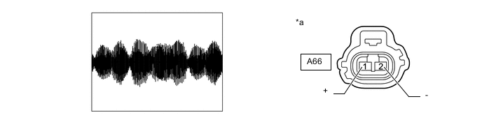
*a Front view of wire harness connector
(to Vehicle Approaching Speaker Assembly)
- -
-
Disconnect the vehicle approaching speaker assembly connector.
-
Connect the GTS to the DLC3.
-
Turn the power switch on (IG).
-
Turn the GTS on.
-
Enter the following menus: Body Electrical / Vehicle Proximity Notification System / Active Test.
-
Perform the Active Test according to the display on the GTS.
Body Electrical > Vehicle Proximity Notification System > Active TestTester Display Measurement Item Control Range Diagnostic Note Proximity Sound (Vehicle Stationary) Proximity sound (Vehicle stationary) OFF or ON Produces warning sound when vehicle is stopped
Body Electrical > Vehicle Proximity Notification System > Active TestTester Display Proximity Sound (Vehicle Stationary) -
Check the signal waveform according to the condition(s) in the table below.
Item Condition Tester Connection A66-1 (+) - A66-2 (-) Tool Setting 1 V/DIV, 200 ms./DIV Vehicle Condition Vehicle approaching speaker operating OK The waveform is similar to that shown in the illustration. Result Proceed to OK NG
NG
REPLACE VEHICLE APPROACHING SPEAKER CONTROLLER Click here
OK
-
-
INSPECT VEHICLE APPROACHING SPEAKER ASSEMBLY
Note
-
Make sure that there is no looseness, rattling, or other problem with the vehicle approaching speaker assembly installation.
-
Make sure that there is no foreign matter inside the vehicle approaching speaker assembly.
-
Remove the vehicle approaching speaker assembly.
-
Inspect the vehicle approaching speaker assembly.
Result Proceed to OK NG
OK
USE SIMULATION METHOD TO CHECK Click here
NG
REPLACE VEHICLE APPROACHING SPEAKER ASSEMBLY Click here
-
-
CHECK STOP LIGHT OPERATION
-
Check that the stop lights come on when the brake pedal is depressed, and go off when the brake pedal is released.
OK Stop lights illuminate properly. Result Result OK NG
NG
GO TO LIGHTING SYSTEM Click here
OK
-
-
CHECK HARNESS AND CONNECTOR (VEHICLE APPROACHING SPEAKER CONTROLLER - STOP LIGHT SWITCH ASSEMBLY)
-
Disconnect the A67 vehicle approaching speaker controller connector.
-
Disconnect the A1 stop light switch assembly connector.
-
Disconnect the A60 hybrid vehicle control ECU connector.
-
Disconnect the I22 shift lock control unit assembly (shift lock control ECU) connector.
-
Disconnect the A57 brake booster with master cylinder assembly connector.
-
Disconnect the I51 certification ECU (smart key ECU assembly) connector.
-
Disconnect the I19 driving support ECU assembly connector.
-
Measure the resistance according to the value(s) in the table below.
Standard Resistance Tester Connection Condition Specified Condition A67-2 (STP) - A1-2 (L) Always Below 1 Ω A67-2 (STP) or A1-2 (L) - Body ground Always 10 kΩ or higher Result Proceed to OK NG
OK
REPLACE VEHICLE APPROACHING SPEAKER CONTROLLER Click here
NG
REPAIR OR REPLACE HARNESS OR CONNECTOR
-
-
CHECK HARNESS AND CONNECTOR (VEHICLE APPROACHING SPEAKER CONTROLLER - COMBINATION METER ASSEMBLY)
-
Disconnect the A67 vehicle approaching speaker controller connector.
-
Disconnect the I10 combination meter assembly connector.
-
Measure the resistance according to the value(s) in the table below.
Standard Resistance Tester Connection Condition Specified Condition A67-6 (SPD) - I10-19 (+S) Always Below 1 Ω A67-6 (SPD) or I10-19 (+S) - Body ground Always 10 kΩ or higher Result Proceed to OK NG
NG
REPAIR OR REPLACE HARNESS OR CONNECTOR
OK
-
-
CHECK COMBINATION METER ASSEMBLY
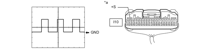
*a Component with harness connected
(Combination Meter Assembly)
- -
-
Check the input waveform.
-
Remove the combination meter assembly with the connector(s) still connected.
-
Connect an oscilloscope to terminal I10-19 (+S) and body ground.
-
Turn the power switch on (IG).
-
Turn a wheel slowly.
-
Check the signal waveform according to the condition(s) in the table below.
Item Condition Tester Connection I10-19 (+S) - Body ground Tool Setting 5 V/DIV, 20 ms./DIV Vehicle Condition Power switch on (IG), wheel being rotated OK The waveform is similar to that shown in the illustration. Tech Tips
When the system is functioning normally, one wheel revolution generates 4 pulses. As the vehicle speed increases, the width indicated by (A) in the illustration narrows.
Result Proceed to OK NG -
OK
REPLACE VEHICLE APPROACHING SPEAKER CONTROLLER Click here
NG
GO TO METER / GAUGE SYSTEM Click here
-
-
CHECK VEHICLE APPROACHING SPEAKER CONTROLLER (PERMISSION SIGNAL)
-
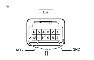
*a Component with harness connected
(Vehicle Approaching Speaker Controller)
Measure the voltage according to the value(s) in the table below.
Standard Voltage Tester Connection Condition Specified Condition A67-11 (KOK) - A67-7 (GND) Power switch on (READY), shift lever in P Below 2.3 V Power switch on (READY), engine stopped and shift lever not in P 8 V or higher Result Result OK NG
OK
REPLACE VEHICLE APPROACHING SPEAKER CONTROLLER Click here
NG
-
-
CHECK VEHICLE APPROACHING SPEAKER CONTROLLER (PERMISSION SIGNAL)
-
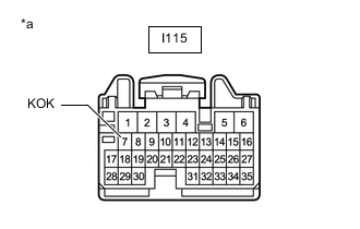
*a Front view of wire harness connector
(to Hybrid Vehicle Control ECU)
Disconnect the hybrid vehicle control ECU connector.
-
Measure the voltage according to the value(s) in the table below.
Standard Voltage Tester Connection Switch Condition Specified Condition I115-7 (KOK) - Body ground Power switch on (IG) 8 V or higher Result Result OK NG
OK
REPLACE HYBRID VEHICLE CONTROL ECU Click here
NG
-
-
CHECK HARNESS AND CONNECTOR (VEHICLE APPROACHING SPEAKER CONTROLLER - HYBRID VEHICLE CONTROL ECU)
-
Disconnect the A67 vehicle approaching speaker controller connector.
-
Disconnect the I115 hybrid vehicle control ECU connector.
-
Measure the resistance according to the value(s) in the table below.
Standard Resistance Tester Connection Condition Specified Condition A67-11 (KOK) - I115-7 (KOK) Always Below 1 Ω A67-11 (KOK) or I115-7 (KOK) - Body ground Always 10 kΩ or higher Result Proceed to OK NG
OK
REPLACE VEHICLE APPROACHING SPEAKER CONTROLLER Click here
NG
REPAIR OR REPLACE HARNESS OR CONNECTOR
-