STOP LIGHT SWITCH INSTALLATION
CAUTION / NOTICE / HINT
Tech Tips
-
Use the same procedure for RHD and LHD vehicles.
-
The procedure listed below is for LHD vehicles.
PROCEDURE
-
INSTALL STOP LIGHT SWITCH MOUNTING ADJUSTER (for RHD)
-
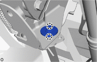
Attach the 2 claws to install a new stop light switch mounting adjuster.
-
-
INSTALL STOP LIGHT SWITCH ASSEMBLY
-
for LHD:
-
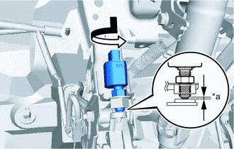
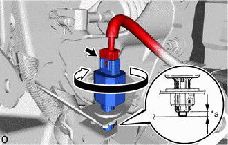
*a Protrusion Amount Measurement Area Turn the stop light switch assembly in the clockwise direction until it reaches the standard shaft protrusion amount and temporarily install it.
Standard 0.5 to 1.7 mm (0.0197 to 0.0669 in.) Note
Do not depress the brake pedal.
-
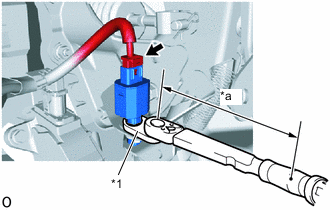
*1 Union Nut Wrench *a Torque Wrench Fulcrum Length Using a union nut wrench and a torque wrench, tighten the lock nut.
Torque Specified tightening torque 16.7 N*m (170 kgf*cm, 12 ft.*lbf) Tech Tips
-
Calculate the torque wrench reading when changing the fulcrum length of the torque wrench.
-
When using union nut wrench (fulcrum length of 30 mm (1.18 in.)) + torque wrench (fulcrum length of 180 mm (7.09 in.)): 14.4 N*m (147 kgf*cm, 11 ft.*lbf)
-
-
Connect the connector.
-
-
for RHD:
-
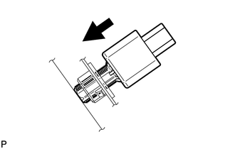
Insert the stop light switch assembly to the stop light switch mounting adjuster until the switch body slightly touches the brake pedal.
Note
Do not depress the brake pedal.
-
*a Protrusion Amount Measurement Area Rotate the stop light switch assembly clockwise by approximately one fourth of a rotation.
-
Check the protrusion amount of the shaft.
Standard 0.5 to 2.6 mm (0.0197 to 0.1024 in.) -
Connect the connector.
-
-
-
INSTALL NO. 1 INSTRUMENT PANEL UNDER COVER SUB-ASSEMBLY
-
INSTALL COWL SIDE TRIM BOARD LH
-
INSTALL DOOR SCUFF PLATE ASSEMBLY LH
-
INSPECT STOP LIGHT
-
Depress the brake pedal and check that the brake light illuminates.
-