LIGHTING SYSTEM Power Source Circuit
DESCRIPTION
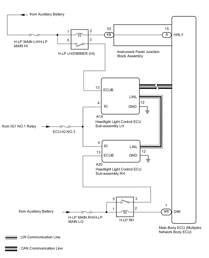
The main body ECU (multiplex network body ECU) receives IG signals and supplies power to the headlight light control ECU sub-assembly via the H-LP relay.
WIRING DIAGRAM
CAUTION / NOTICE / HINT
Note
-
Inspect the fuses for circuits related to this system before performing the following inspection procedure.
-
If the main body ECU (multiplex network body ECU) is replaced, refer to Service Bulletin.
PROCEDURE
-
CHECK HARNESS AND CONNECTOR (HEADLIGHT LIGHT CONTROL ECU SUB-ASSEMBLY - BATTERY AND BODY GROUND)
-
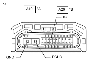
*A Headlight light control ECU sub-assembly LH *B Headlight light control ECU sub-assembly RH *a Front view of wire harness connector
(Headlight light control ECU sub-assembly)
Disconnect the A19 headlight light control ECU sub-assembly LH or A20 headlight light control ECU sub-assembly RH connector.
-
Measure the voltage according to the value(s) in the table below.
Standard Voltage Headlight light control ECU sub-assembly LH Tester Connection Switch Condition Specified Condition A19-13 (ECUB) - Body ground Headlight on 11 to 14 V A19-4 (IG) - Body ground Power switch on (IG) 11 to 14 V Headlight light control ECU sub-assembly RH Tester Connection Switch Condition Specified Condition A20-13 (ECUB) - Body ground Headlight on 11 to 14 V A20-4 (IG) - Body ground Power switch on (IG) 11 to 14 V -
Measure the resistance according to the value(s) in the table below.
Standard Resistance Headlight light control ECU sub-assembly LH Tester Connection Condition Specified Condition A19-12 (GND) - Body ground Always Below 1 Ω Headlight light control ECU sub-assembly RH Tester Connection Condition Specified Condition A20-12 (GND) - Body ground Always Below 1 Ω Result Proceed to OK NG (Headlight Light Control ECU Sub-assembly LH) NG (Headlight Light Control ECU Sub-assembly RH)
OK 
PROCEED TO NEXT SUSPECTED AREA SHOWN IN PROBLEM SYMPTOMS TABLE Click here
NG (Headlight Light Control ECU Sub-assembly RH) 
CHECK HEADLIGHT RELAY (H-LP RH) Click here
NG (Headlight Light Control ECU Sub-assembly LH) 
-
-
INSPECT HEADLIGHT DIMMER RELAY (H-LP LH/DIMMER [HI])
-
Remove the headlight light dimmer relay (H-LP LH/DIMMER [HI]) from the engine room relay block.
-
Inspect the headlight light dimmer relay (H-LP LH/DIMMER [HI]).
Result Proceed to OK NG
NG
REPLACE HEADLIGHT DIMMER RELAY (H-LP LH/DIMMER [HI])
OK
-
-
CHECK HARNESS AND CONNECTOR (HEADLIGHT DIMMER RELAY [H-LP LH/DIMMER (HI)] - BATTERY)
-
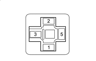
*a Front view of wire harness connector
(to Headlight Light Dimmer Relay (H-LP LH/DIMMER [HI])
Remove the headlight light dimmer relay (H-LP LH/DIMMER [HI]) from the engine room relay block.
-
Measure the voltage according to the value(s) in the table below.
Standard Voltage Tester Connection Switch Condition Specified Condition Relay terminal 1 - Body ground Power switch off 11 to 14 V Relay terminal 5 - Body ground Power switch off 11 to 14 V Result Proceed to OK NG
NG
REPAIR OR REPLACE HARNESS OR CONNECTOR
OK
-
-
CHECK HARNESS AND CONNECTOR (HEADLIGHT DIMMER RELAY [H-LP LH/DIMMER (HI)] - HEADLIGHT LIGHT CONTROL ECU SUB-ASSEMBLY LH)
-
Remove the headlight light dimmer relay (H-LP LH/DIMMER [HI]) from the engine room relay block.
-
Disconnect the A19 headlight light control ECU LH sub-assembly LH connector.
-
Measure the resistance according to the value(s) in the table below.
Standard Resistance Tester Connection Condition Specified Condition Relay terminal 3 - A19-13 (ECUB) Always Below 1 Ω Relay terminal 3 or A19-13 (ECUB) - Body ground Always 10 kΩ or higher Result Proceed to OK NG
NG
REPAIR OR REPLACE HARNESS OR CONNECTOR
OK
-
-
CHECK HARNESS AND CONNECTOR (HEADLIGHT DIMMER RELAY [H-LP LH/DIMMER (HI)] - MAIN BODY ECU [MULTIPLEX NETWORK BODY ECU])
-
Remove the headlight light dimmer relay (H-LP LH/DIMMER [HI]) from the engine room relay block.
-
Remove the instrument panel junction block assembly.
for LHD:
for RHD:
-
Remove the main body ECU (multiplex network body ECU) from the instrument panel junction block assembly.
for LHD:
for RHD:
-
Disconnect the 4B instrument panel junction block assembly connector.
-
Measure the resistance according to the value(s) in the table below.
Standard Resistance Tester Connection Condition Specified Condition Relay terminal 2 - A-15 (HRLY) Always Below 1 Ω Relay terminal 2 or A-15 (HRLY) - Body ground Always 10 kΩ or higher Result Proceed to OK NG
OK
REPLACE MAIN BODY ECU (MULTIPLEX NETWORK BODY ECU) for LHD: REPLACE MAIN BODY ECU (MULTIPLEX NETWORK BODY ECU) Click here
REPLACE MAIN BODY ECU (MULTIPLEX NETWORK BODY ECU) for RHD: REPLACE MAIN BODY ECU (MULTIPLEX NETWORK BODY ECU) Click hereNG
-
-
CHECK HARNESS AND CONNECTOR (HEADLIGHT DIMMER RELAY [H-LP LH/DIMMER (HI)] - INSTRUMENT PANEL JUNCTION BLOCK ASSEMBLY)
-
Remove the headlight light dimmer relay (H-LP LH/DIMMER [HI]) from the engine room relay block.
-
Disconnect the 4B instrument panel junction block assembly connector.
-
Measure the resistance according to the value(s) in the table below.
Standard Resistance Tester Connection Condition Specified Condition Relay terminal 2 - 4B-53 Always Below 1 Ω Relay terminal 2 or 4B-53 - Body ground Always 10 kΩ or higher Result Proceed to OK NG
OK
REPLACE INSTRUMENT PANEL JUNCTION BLOCK ASSEMBLY for LHD: REPLACE INSTRUMENT PANEL JUNCTION BLOCK ASSEMBLY Click here
REPLACE INSTRUMENT PANEL JUNCTION BLOCK ASSEMBLY for RHD: REPLACE INSTRUMENT PANEL JUNCTION BLOCK ASSEMBLY Click hereNG
REPAIR OR REPLACE HARNESS OR CONNECTOR
-
-
CHECK HEADLIGHT RELAY (H-LP RH)
-
Remove the headlight relay (H-LP RH) from the No. 2 engine room relay block.
-
Inspect the headlight light relay (H-LP RH).
Result Proceed to OK NG
NG
REPLACE HEADLIGHT RELAY (H-LP RH RELAY)
OK
-
-
CHECK HARNESS AND CONNECTOR (HEADLIGHT RELAY [H-LP RH] - BATTERY)
-
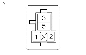
*a Front view of wire harness connector
(to Headlight Relay [H-LP RH])
Remove the headlight relay (H-LP RH) from the No. 2 engine room relay block.
-
Measure the voltage according to the value(s) in the table below.
Standard Voltage Tester Connection Switch Condition Specified Condition Relay terminal 1 - Body ground Power switch off 11 to 14 V Relay terminal 5 - Body ground Power switch off 11 to 14 V Result Proceed to OK NG
NG
REPAIR OR REPLACE HARNESS OR CONNECTOR
OK
-
-
CHECK HARNESS AND CONNECTOR (HEADLIGHT RELAY [H-LP RH RELAY] - HEADLIGHT LIGHT CONTROL ECU ASSEMBLY RH AND MAIN BODY ECU [MULTIPLEX NETWORK BODY ECU])
-
Remove the headlight relay (H-LP RH) from the No. 2 engine room relay block.
-
Disconnect the A20 headlight light control ECU RH sub-assembly LH connector.
-
Disconnect the I48 main body ECU (multiplex network body ECU) connector.
-
Measure the resistance according to the value(s) in the table below.
Standard Resistance Tester Connection Condition Specified Condition Relay terminal 3 - A20-13 (ECUB) Always Below 1 Ω Relay terminal 2 - I48-1 (DIM) Always Below 1 Ω Relay terminal 3 or A20-13 (ECUB) - Body ground Always 10 kΩ or higher Relay terminal 2 or I48-1 (DIM) - Body ground Always 10 kΩ or higher Result Proceed to OK NG
OK
REPLACE MAIN BODY ECU (MULTIPLEX NETWORK BODY ECU) for LHD: REPLACE MAIN BODY ECU (MULTIPLEX NETWORK BODY ECU) Click here
REPLACE MAIN BODY ECU (MULTIPLEX NETWORK BODY ECU) for RHD: REPLACE MAIN BODY ECU (MULTIPLEX NETWORK BODY ECU) Click hereNG
REPAIR OR REPLACE HARNESS OR CONNECTOR
-