LIGHTING SYSTEM Front Fog Light Circuit
DESCRIPTION
Illumination of the front fog lights is controlled by the main body ECU (multiplex network body ECU).
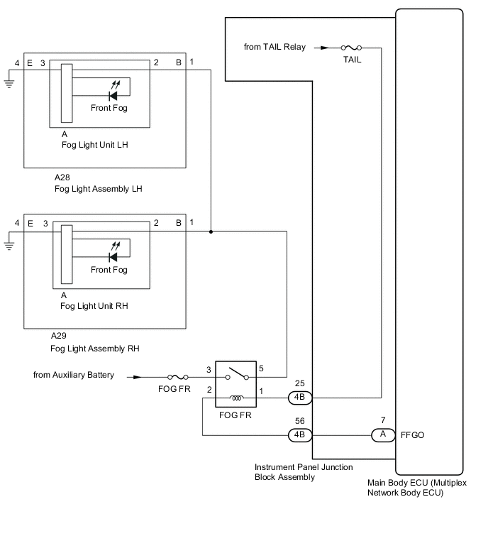
WIRING DIAGRAM
CAUTION / NOTICE / HINT
Note
-
Inspect the fuses for circuits related to this system before performing the following inspection procedure.
-
Before performing troubleshooting, check that the taillight circuit operates properly.
-
If the main body ECU (multiplex network body ECU) is replaced, refer to Service Bulletin.
PROCEDURE
-
PERFORM ACTIVE TEST USING GTS (FRONT FOG LIGHT RELAY)
-
Using the GTS, perform the Active Test.
Body Electrical > Main Body > Active TestTester Display Measurement Item Control Range Diagnostic Note Front Fog Light Relay Front fog light relay ON or OFF The headlight dimmer switch is in the tail position
Body Electrical > Main Body > Active TestTester Display Front Fog Light Relay Result Result Proceed to The Active Test is performed normally A The Active Test is not performed normally for both fog lights B The Active Test is not performed normally for the right side fog light only C The Active Test is not performed normally for the left side fog light only D
A 
PROCEED TO NEXT SUSPECTED AREA SHOWN IN PROBLEM SYMPTOMS TABLE Click here
C 
CHECK HARNESS AND CONNECTOR (FRONT FOG LIGHT RELAY [FOG FR] - FOG LIGHT ASSEMBLY RH) Click here
D
CHECK HARNESS AND CONNECTOR (FRONT FOG LIGHT RELAY [FOG FR] - FOG LIGHT ASSEMBLY LH) Click here
B 
-
-
CHECK FRONT FOG LIGHT RELAY (FOG FR)
-
Remove the front fog light relay from the No. 2 engine room relay block.
-
Inspect the fog light relay.
Result Proceed to OK NG
NG
REPLACE FOG LIGHT RELAY (FOG FR)
OK
-
-
CHECK HARNESS AND CONNECTOR (FRONT FOG LIGHT RELAY [FR FOG] - BATTERY)
-
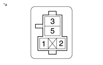
*a Front view of wire harness connector
(to Front Fog Light Relay [FR FOG])
Remove the front fog light relay from the No. 2 engine room relay block.
-
Measure the voltage according to the value(s) in the table below.
Standard Voltage Tester Connection Switch Condition Specified Condition Relay terminal 3 - Body ground Power switch off 11 to 14 V Result Proceed to OK NG
NG
REPAIR OR REPLACE HARNESS OR CONNECTOR
OK
-
-
CHECK HARNESS AND CONNECTOR (TAILLIGHT RELAY [TAIL RELAY] - FRONT FOG LIGHT RELAY [FOG FR])
-

*a Front view of wire harness connector
(to Front Fog Light Relay [FOG FR])
Remove the front fog light relay from the No. 2 engine room relay block.
-
Measure the voltage according to the value(s) in the table below.
Standard Voltage If the low beams are illuminated, shine a light on the automatic light control sensor to change the system to daytime mode.Tester Connection Switch Condition Specified Condition Relay terminal 1 - Body ground
-
Headlight dimmer switch off → TAIL or HEAD (When vehicle has the dimmer switch off position)
-
Headlight dimmer switch in AUTO with low beams off → low beams on
Below 1 V → 11 to 14 V
Result Proceed to OK NG -
NG
CHECK HARNESS AND CONNECTOR (FRONT FOG LIGHT RELAY [FOG FR] - INSTRUMENT PANEL JUNCTION BLOCK ASSEMBLY) Click here
OK
-
-
CHECK HARNESS AND CONNECTOR (FRONT FOG LIGHT RELAY [FOG FR] - FOG LIGHT ASSEMBLY AND BODY GROUND)
-
Remove the front fog light relay from the No. 2 engine room relay block.
-
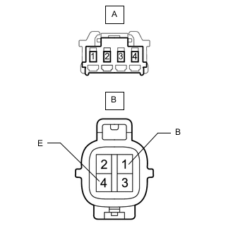
Disconnect the A28 fog light assembly LH connector.
-
Disconnect the A29 fog light assembly RH connector.
-
Measure the resistance according to the value(s) in the table below.
Standard Resistance Tester Connection Condition Specified Condition Relay terminal 5 - A28-1 (B) Always Below 1 Ω Relay terminal 5 - A29-1 (B) Always Below 1 Ω A28-4 (E) - Body ground Always Below 1 Ω A29-4 (E) - Body ground Always Below 1 Ω Relay terminal 5 or A28-1 (B) - Body ground Always 10 kΩ or higher Relay terminal 5 or A29-1 (B) - Body ground Always 10 kΩ or higher Result Proceed to OK NG
NG
REPAIR OR REPLACE HARNESS OR CONNECTOR
OK
-
-
CHECK HARNESS AND CONNECTOR (FRONT FOG LIGHT RELAY [FOG FR] - MAIN BODY ECU [MULTIPLEX NETWORK BODY ECU])
-
Remove the front fog light relay from the No. 2 engine room relay block.
-
Remove the instrument panel junction block assembly.
for LHD:
for RHD:
-
Remove the main body ECU (multiplex network body ECU) from the instrument panel junction block assembly.
for LHD:
for RHD:
-
Disconnect the 4B instrument panel junction block assembly connector.
-
Measure the resistance according to the value(s) in the table below.
Standard Resistance Tester Connection Condition Specified Condition Relay terminal 2 - A-7 (FFGO) Always Below 1 Ω Relay terminal 2 or A-7 (FFGO) - Body ground Always 10 kΩ or higher Result Proceed to OK NG
OK
REPLACE MAIN BODY ECU (MULTIPLEX NETWORK BODY ECU) for LHD: REPLACE MAIN BODY ECU (MULTIPLEX NETWORK BODY ECU) Click here
REPLACE MAIN BODY ECU (MULTIPLEX NETWORK BODY ECU) for RHD: REPLACE MAIN BODY ECU (MULTIPLEX NETWORK BODY ECU) Click hereNG
CHECK HARNESS AND CONNECTOR (FRONT FOG LIGHT RELAY [FOG FR] - INSTRUMENT PANEL JUNCTION BLOCK ASSEMBLY) Click here
-
-
CHECK HARNESS AND CONNECTOR (FRONT FOG LIGHT RELAY [FOG FR] - INSTRUMENT PANEL JUNCTION BLOCK ASSEMBLY)
-
Remove the front fog light relay from the No. 2 engine room relay block.
-
Disconnect the 4B instrument panel junction block assembly connector.
-
Measure the resistance according to the value(s) in the table below.
Standard Resistance Tester Connection Condition Specified Condition Relay terminal 1 - 4B-25 Always Below 1 Ω Relay terminal 1 or 4B-25 - Body ground Always 10 kΩ or higher Result Proceed to OK NG
OK
REPLACE INSTRUMENT PANEL JUNCTION BLOCK ASSEMBLY for LHD: REPLACE INSTRUMENT PANEL JUNCTION BLOCK ASSEMBLY Click here
REPLACE INSTRUMENT PANEL JUNCTION BLOCK ASSEMBLY for RHD: REPLACE INSTRUMENT PANEL JUNCTION BLOCK ASSEMBLY Click hereNG
REPAIR OR REPLACE HARNESS OR CONNECTOR
-
-
CHECK HARNESS AND CONNECTOR (FRONT FOG LIGHT RELAY [FOG FR] - INSTRUMENT PANEL JUNCTION BLOCK ASSEMBLY)
-
Remove the front fog light relay from the No. 2 engine room relay block.
-
Disconnect the 4B instrument panel junction block assembly connector.
-
Measure the resistance according to the value(s) in the table below.
Standard Resistance Tester Connection Condition Specified Condition Relay terminal 2 - 4B-56 Always Below 1 Ω Relay terminal 2 or 4B-56 - Body ground Always 10 kΩ or higher Result Proceed to OK NG
OK
REPLACE INSTRUMENT PANEL JUNCTION BLOCK ASSEMBLY for LHD: REPLACE INSTRUMENT PANEL JUNCTION BLOCK ASSEMBLY Click here
REPLACE INSTRUMENT PANEL JUNCTION BLOCK ASSEMBLY for RHD: REPLACE INSTRUMENT PANEL JUNCTION BLOCK ASSEMBLY Click hereNG
REPAIR OR REPLACE HARNESS OR CONNECTOR
-
-
CHECK HARNESS AND CONNECTOR (FRONT FOG LIGHT RELAY [FOG FR] - FOG LIGHT ASSEMBLY RH)
-
Remove the front fog light relay from the No. 2 engine room relay block.
-
Disconnect the A29 fog light assembly RH connector.
-
Measure the resistance according to the value(s) in the table below.
Standard Resistance Tester Connection Condition Specified Condition Relay terminal 5 - A29-1 (B) Always Below 1 Ω A29-4 (E) - Body ground Always Below 1 Ω Relay terminal 5 or A29-1 (B) - Body ground Always 10 kΩ or higher Result Proceed to OK NG
NG
REPAIR OR REPLACE HARNESS OR CONNECTOR
OK
-
-
INSPECT FOG LIGHT ASSEMBLY RH
-
Remove the fog light assembly RH.
-
Remove the fog light unit RH from the fog light assembly RH.
-
Measure the resistance according to the value(s) in the table below.
Standard Resistance Tester Connection Condition Specified Condition A-2 - B-1 (B) Always Below 1 Ω A-3 - B-4 (E) Always 10 kΩ or higher Result Proceed to OK NG
OK
REPLACE FOG LIGHT UNIT RH Click here
NG
REPLACE FOG LIGHT ASSEMBLY RH Click here
-
-
CHECK HARNESS AND CONNECTOR (FRONT FOG LIGHT RELAY [FOG FR] - FOG LIGHT ASSEMBLY LH)
-
Remove the front fog light relay from the No. 2 engine room relay block.
-
Disconnect the A28 fog light assembly LH connector.
-
Measure the resistance according to the value(s) in the table below.
Standard Resistance Tester Connection Condition Specified Condition Relay terminal 5 - A28-1 (B) Always Below 1 Ω A28-4 (E) - Body ground Always Below 1 Ω Relay terminal 5 or A28-1 (B) - Body ground Always 10 kΩ or higher Result Proceed to OK NG
NG
REPAIR OR REPLACE HARNESS OR CONNECTOR
OK
-
-
INSPECT FOG LIGHT ASSEMBLY LH
-
Remove the fog light assembly LH.
-
Remove the fog light unit LH from the fog light assembly LH.
-
Measure the resistance according to the value(s) in the table below.
Standard Resistance Tester Connection Condition Specified Condition A-2 - B-1 (B) Always Below 1 Ω A-3 - B-4 (E) Always 10 kΩ or higher Result Proceed to OK NG
OK
REPLACE FOG LIGHT UNIT LH Click here
NG
REPLACE FOG LIGHT ASSEMBLY LH Click here
-