LIGHTING SYSTEM, Diagnostic DTC:U0242
| DTC Code | DTC Name |
|---|---|
| U0242 | Lost Communication With Headlamp Control Module "B" |
DESCRIPTION
| DTC No. | Detection Item | DTC Detection Condition | Trouble Area |
|---|---|---|---|
| U0242 | Lost Communication With Headlamp Control Module "B" | Either of the following conditions is met:
|
|
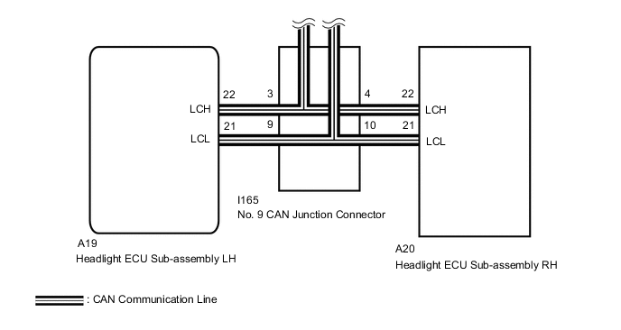
WIRING DIAGRAM
-
for Triple Beam Headlight with Adaptive High Beam System
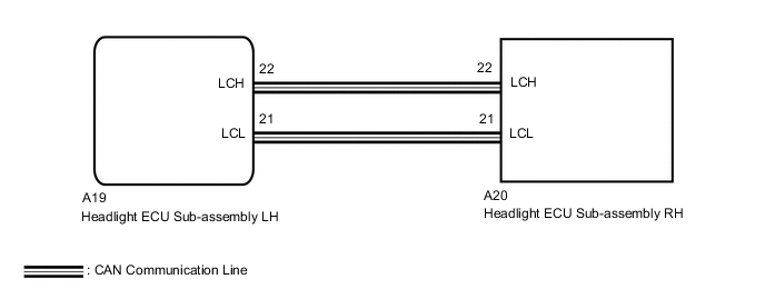
-
for Triple Beam Headlight without Adaptive High Beam System, for Single Beam Headlight
CAUTION / NOTICE / HINT
Note
After the headlight ECU sub-assembly LH is replaced, vehicle information registration and initialization are necessary.
PROCEDURE
-
CONFIRM MODEL
-
Choose the model to be inspected.
Result Result Proceed to for Triple Beam Headlight with Adaptive High Beam System A for Triple Beam Headlight without Adaptive High Beam System B for Single Beam Headlight
B 
CHECK FOR DTC Click here
A 
-
-
CHECK FOR DTC
-
Clear the DTCs.
Body Electrical > AFS > Clear DTCs -
Check for DTCs.
Body Electrical > AFS > Trouble CodesOK DTC U0242 is not output. Result Proceed to OK NG
OK 
USE SIMULATION METHOD TO CHECK Click here
NG
-
-
CHECK FOR DTC
-
Turn the power switch on (IG).
-
Check for DTCs.
Body Electrical > Pre-Collision 2 > Trouble CodesOK DTC U1002 is not output. Result Proceed to OK NG
NG
GO TO DTC U1002 Click here
OK
-
-
CHECK CAN BUS WIRES (HEADLIGHT ECU SUB-ASSEMBLY LH)
-

*a Front view of wire harness connector
(to Headlight ECU Sub-assembly LH)
Disconnect the cable from the negative (-) battery terminal.
-
Disconnect the headlight ECU sub-assembly LH connector.
-
Measure the resistance according to the value(s) in the table below.
Standard Resistance Tester Connection Condition Specified Condition A19-21 (LCL) - A19-22 (LCH) Cable disconnected from negative (-) auxiliary battery terminal 54 to 69 Ω -
Reconnect the headlight ECU sub-assembly LH connector.
Result Proceed to OK NG
OK
REPLACE HEADLIGHT ECU SUB-ASSEMBLY LH Click here
NG
-
-
CHECK CAN BUS WIRES (HEADLIGHT ECU SUB-ASSEMBLY RH)
-
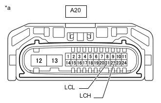
*a Front view of wire harness connector
(to Headlight ECU Sub-assembly RH)
Disconnect the headlight ECU sub-assembly RH connector.
-
Measure the resistance according to the value(s) in the table below.
Standard Resistance Tester Connection Condition Specified Condition A20-21 (LCL) - A20-22 (LCH) Cable disconnected from negative (-) auxiliary battery terminal 54 to 69 Ω Result Proceed to OK NG
OK
REPLACE HEADLIGHT ECU SUB-ASSEMBLY RH Click here
NG
-
-
CHECK HEADLIGHT ECU SUB-ASSEMBLY RH
-
Replace the headlight light ECU sub-assembly LH with a new.
-
Clear the DTCs.
Body Electrical > AFS > Clear DTCs -
Check for DTCs.
Body Electrical > AFS > Trouble CodesOK DTC U0242 is not output. Result Proceed to OK NG
OK
END (HEADLIGHT ECU SUB-ASSEMBLY RH WAS DEFECTIVE)
NG
REPLACE HEADLIGHT ECU SUB-ASSEMBLY LH Click here
-
-
CHECK FOR DTC
-
Clear the DTCs.
for Single Beam Headlight:
Body Electrical > HL AutoLeveling > Clear DTCsfor Triple Beam Headlight:
Body Electrical > AFS > Clear DTCs -
Check for DTCs.
for Single Beam Headlight:
Body Electrical > HL AutoLeveling > Trouble Codesfor Triple Beam Headlight:
Body Electrical > AFS > Trouble CodesOK DTC U0242 is not output. Result Proceed to OK NG
OK
USE SIMULATION METHOD TO CHECK Click here
NG
-
-
CHECK CAN BUS WIRES (HEADLIGHT ECU SUB-ASSEMBLY LH)
-
*a Front view of wire harness connector
(to Headlight ECU Sub-assembly LH)
Disconnect the cable from the negative (-) battery terminal.
-
Disconnect the headlight ECU sub-assembly LH connector.
-
Measure the resistance according to the value(s) in the table below.
Standard Resistance Tester Connection Condition Specified Condition A19-21 (LCL) - A19-22 (LCH) Cable disconnected from negative (-) auxiliary battery terminal 108 to 132 Ω A19-21 (LCL) - GND Cable disconnected from negative (-) auxiliary battery terminal 200 Ω or higher A19-22 (LCH) - GND Cable disconnected from negative (-) auxiliary battery terminal 200 Ω or higher A19-21 (LCL) - +B Cable disconnected from negative (-) auxiliary battery terminal 6 kΩ or higher A19-22 (LCH) - +B Cable disconnected from negative (-) auxiliary battery terminal 6 kΩ or higher -
Reconnect the headlight ECU sub-assembly LH connector.
Result Proceed to OK NG
OK
REPLACE HEADLIGHT ECU SUB-ASSEMBLY LH Click here
NG
-
-
CHECK CAN BUS WIRES (HEADLIGHT ECU SUB-ASSEMBLY RH)
-
*a Front view of wire harness connector
(to Headlight ECU Sub-assembly RH)
Disconnect the headlight ECU sub-assembly RH connector.
-
Measure the resistance according to the value(s) in the table below.
Standard Resistance Tester Connection Condition Specified Condition A20-21 (LCL) - A20-22 (LCH) Cable disconnected from negative (-) auxiliary battery terminal 108 to 132 Ω A20-21 (LCL) - GND Cable disconnected from negative (-) auxiliary battery terminal 200 Ω or higher A20-22 (LCH) - GND Cable disconnected from negative (-) auxiliary battery terminal 200 Ω or higher A20-21 (LCL) - +B Cable disconnected from negative (-) auxiliary battery terminal 6 kΩ or higher A20-22 (LCH) - +B Cable disconnected from negative (-) auxiliary battery terminal 6 kΩ or higher Result Proceed to OK NG
OK
REPLACE HEADLIGHT ECU SUB-ASSEMBLY RH Click here
NG
REPAIR OR REPLACE CAN MAIN WIRE OR CONNECTOR
-