WIPER AND WASHER SYSTEM Washer Fluid Level Warning Switch Circuit
DESCRIPTION
When the volume of washer fluid decreases to below a certain level (when the level warning switch assembly is turned on), the multi-information display warns the driver by displaying a message.
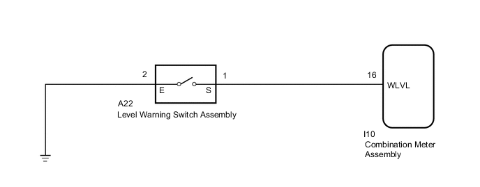
WIRING DIAGRAM
CAUTION / NOTICE / HINT
Note
When replacing the combination meter assembly, make sure to replace it with a new one.
PROCEDURE
-
READ VALUE USING GTS
-
Read the Data List according to the display on the GTS.
Body Electrical > Combination Meter > Data ListTester Display Measurement Item Range Normal Condition Diagnostic Note Washer Switch Level warning switch condition ON/OFF ON: Fluid volume is less than 600 to 800 cc (36.6 to 48.8 cu.in.)
OFF: Fluid volume is more than 600 to 800 cc (36.6 to 48.8 cu.in.)
-
Body Electrical > Combination Meter > Data ListTester Display Washer Switch OK On the GTS screen, ON or OFF is displayed accordingly. Result Proceed to OK NG
OK 
GO TO METER / GAUGE SYSTEM Click here
NG 
-
-
INSPECT LEVEL WARNING SWITCH ASSEMBLY
-
Disconnect the A22 level warning switch assembly connector.
-
Inspect the level warning switch assembly.
Result Proceed to OK NG
NG
REPLACE LEVEL WARNING SWITCH ASSEMBLY Click here
OK
-
-
CHECK HARNESS AND CONNECTOR (LEVEL WARNING SWITCH ASSEMBLY - COMBINATION METER ASSEMBLY AND BODY GROUND)
-
Disconnect the A22 level warning switch assembly connector.
-
Disconnect the I10 combination meter assembly connector.
-
Measure the resistance according to the value(s) in the table below.
Standard Resistance Tester Connection Condition Specified Condition A22-1 (S) - I10-16 (WLVL) Always Below 1 Ω A22-2 (E) - Body ground Always Below 1 Ω A22-1 (S) or I10-16 (WLVL) - Body ground Always 10 kΩ or higher Result Proceed to OK NG
OK
REPLACE COMBINATION METER ASSEMBLY Click here
NG
REPAIR OR REPLACE HARNESS OR CONNECTOR
-