FRONT DOOR REASSEMBLY

CAUTION / NOTICE / HINT
Tech Tips
-
Use the same procedure for RHD and LHD vehicles.
-
The procedure listed below is for LHD vehicles.
-
Use the same procedure for the RH and LH sides.
-
The procedure listed below is for the LH side.
-
A bolt without a torque specification is shown in the standard bolt chart.
PROCEDURE
-
REPAIR INSTRUCTION
-
INSTALL NO. 1 BLACK OUT TAPE LH
-
INSTALL NO. 2 BLACK OUT TAPE LH
-
INSTALL NO. 3 BLACK OUT TAPE LH
-
INSTALL FRONT DOOR OUTSIDE MOULDING SUB-ASSEMBLY LH
-
INSTALL FRONT DOOR REAR WINDOW FRAME MOULDING LH
-
INSTALL HOLE PLUG
-
Install the hole plug.
-
-
INSTALL FRONT DOOR PANEL CUSHION
-
Install the 2 front door panel cushions.
-
-
INSTALL FRONT DOOR BELT MOULDING ASSEMBLY LH
-
INSTALL FRONT DOOR UPPER OUTSIDE MOULDING PAD
-
INSTALL FRONT DOOR LOWER OUTSIDE MOULDING SUB-ASSEMBLY LH
-
INSTALL FRONT DOOR WEATHERSTRIP LH
-
Attach the 24 clips to install the front door weatherstrip LH.
-
-
INSTALL UPPER DOOR FRAME GARNISH LH
-
Install a new upper door frame garnish LH.
-
-
INSTALL FRONT DOOR CHECK ASSEMBLY LH
-
Apply MP grease to the sliding area of the front door check assembly LH.
-
When reusing a bolt:
-
Clean the threads of the bolt with non-residue solvent.
-
Apply adhesive to the threads of the bolt.
Adhesive Toyota Genuine Adhesive 1324, Three Bond 1324 or equivalent.
-
-
Install the front door check assembly to the door panel with the 2 nuts.
- Torque:
- 8.0 N*m { 82 kgf*cm, 71 in.*lbf }
-
Install the front door check assembly to the body panel with the bolt.
- Torque:
- 27 N*m { 275 kgf*cm, 20 ft.*lbf }
-
-
INSTALL FRONT DOOR LOCK ASSEMBLY LH
-
INSTALL DOOR OUTSIDE HANDLE BUSH
-
Install the door outside handle bush.
-
-
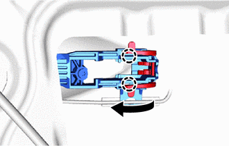
INSTALL FRONT DOOR LOCK OPEN ROD LH
-
Install the front door lock open rod LH to the front door outside handle frame sub-assembly LH.
-
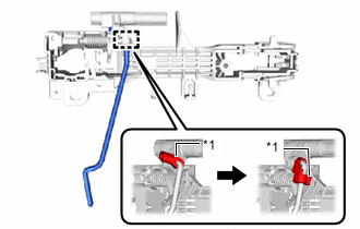
*1 Snap Rotate the snap as shown in the illustration to attach the snap to the front door lock open rod LH.
-
-
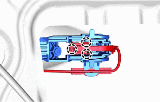
INSTALL FRONT DOOR OUTSIDE HANDLE FRAME SUB-ASSEMBLY LH
-
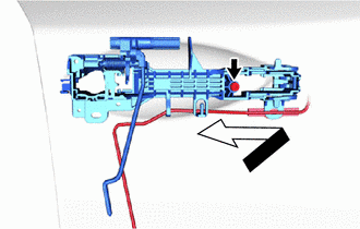
Apply MP grease to the sliding area of the front door outside handle frame sub-assembly LH.
-
Using a T30 "TORX" socket wrench, install the front door outside handle frame sub-assembly LH with the screw as shown in the illustration.
- Torque:
- 4.0 N*m { 41 kgf*cm, 35 in.*lbf }
-
Attach the clamp.
-
-
INSTALL FRONT DOOR FRONT OUTSIDE HANDLE PAD
-
Attach the 3 claws to install the front door front outside handle pad.
-
-
INSTALL FRONT DOOR REAR OUTSIDE HANDLE PAD
-
Attach the 4 claws to install the front door rear outside handle pad.
-
-
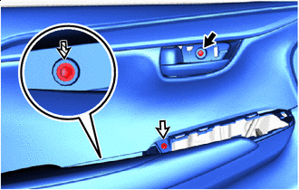
INSTALL FRONT DOOR LOCK CYLINDER ASSEMBLY LH (for Driver Side)
-
Using a mechanical key, temporarily install the front door lock cylinder assembly LH as shown in the illustration.
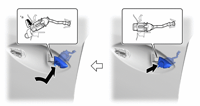
*a 30° - - -
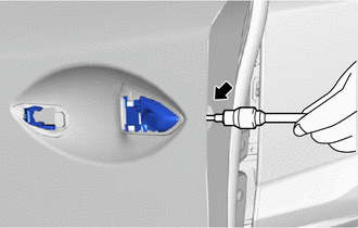
Using a T30 "TORX" socket wrench, install the front door lock cylinder assembly LH with the screw.
-
Install the hole plug.
-
-
INSTALL FRONT DOOR OUTSIDE HANDLE COVER RH (for Front Passenger Side)
-
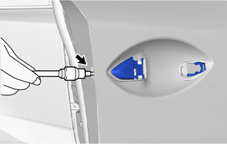
Using a T30 "TORX" socket wrench, install the front door outside handle cover RH with the screw.
-
Install the hole plug.
-
-
INSTALL FRONT DOOR OUTSIDE HANDLE ASSEMBLY LH
-
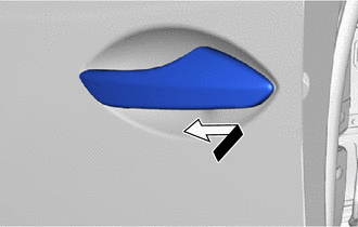
Temporarily install the front door outside handle assembly LH in the direction of the arrow shown in the illustration.
-
Attach the 2 claws to install the holder to the front door outside handle assembly LH.
-
Attach the 3 claws to connect the connector and connector cover.
-
-
INSTALL FRONT DOOR REAR LOWER FRAME SUB-ASSEMBLY LH
-
Attach the guide to install the front door rear lower frame sub-assembly LH with the bolt.
-
-
INSTALL FRONT DOOR NO. 1 STIFFENER CUSHION
-
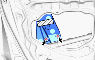

Double-sided tape Clean vehicle installation surface.
-
Remove any remaining double-sided tape from the vehicle installation surface.
-
Clean the front door panel sub-assembly RH installation surface with non-residue solvent.
-
-
Remove the peeling paper on a new front door No. 1 stiffener cushion while making sure not to touch the adhesional surface.
-
Install the front door No. 1 stiffener cushion with the 2 bolts.
- Torque:
- 6.2 N*m { 63 kgf*cm, 55 in.*lbf }
-
Press the front door No. 1 stiffener cushion against the door panel.
-
-
INSTALL FRONT DOOR WINDOW REGULATOR SUB-ASSEMBLY LH
-
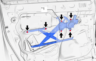
*1 Temporarily Bolt Apply MP grease to the sliding and rotating areas of the front door window regulator sub-assembly LH.
-
Temporarily install the temporarily bolt to the front door window regulator sub-assembly LH.
-
Install the front door window regulator sub-assembly LH with the 5 bolts, and then tighten the temporarily bolt.
- Torque:
- 8.0 N*m { 82 kgf*cm, 71 in.*lbf }
Tech Tips
Tighten the bolts in the order shown in the illustration.
Note
Be careful not to drop the front door window regulator as it may become damaged.
-
-
INSTALL FRONT DOOR FIX WINDOW WEATHERSTRIP LH
-
Install the front door fix window weatherstrip LH.
-
-
INSTALL FRONT DOOR FIX WINDOW GLASS LH
-
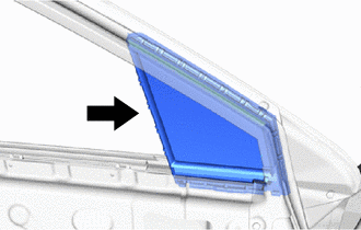
Install the front door fix window glass LH in the direction indicated by the arrow in the illustration.
-
-
INSTALL FRONT DOOR FRONT LOWER FRAME SUB-ASSEMBLY LH
-
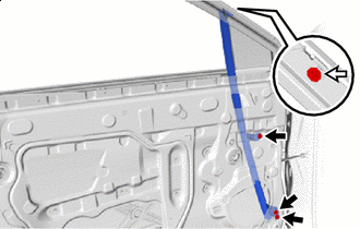

Bolt 
Screw Lift up the weatherstrip, and then install the front door front lower frame sub-assembly LH with the screw.
-
Install the 3 bolts.
- Torque:
- 6.2 N*m { 63 kgf*cm, 55 in.*lbf }
-
-
INSTALL FRONT DOOR GLASS SUB-ASSEMBLY LH
-
Temporarily install the power window regulator master switch assembly with front door armrest base panel.
-
Connect the cable to the auxiliary battery negative (-) terminal.
-
Move the front door window regulator so that the front door glass bolts can be seen.
-
Disconnect the cable from the auxiliary battery negative (-) terminal.
CAUTION:
Wait at least 90 seconds after disconnecting the cable from the auxiliary battery negative (-) terminal to disable the SRS system.
Note
When disconnecting the cable, some systems need to be initialized after the cable is reconnected.
-
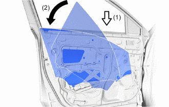
Insert the front door glass sub-assembly LH in the door panel sub-assembly LH in the order shown in the illustration.
Note
Be careful not to damage the front door glass sub-assembly LH.
-
Install the front door glass sub-assembly LH with the 2 bolts.
- Torque:
- 8.0 N*m { 82 kgf*cm, 71 in.*lbf }
-
Install the hole plug.
-
-
INSTALL FRONT DOOR GLASS RUN LH
-
Install the front door glass run LH.
-
-
INSTALL DOOR SIDE AIR BAG SENSOR LH
-
INSTALL FRONT DOOR SERVICE HOLE COVER LH
-
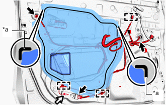
*a Reference Point Connector Bolt Apply new butyl tape to the front door panel.
-
Pass each cable and connector through a new front door service hole cover LH.
-
Attach the front door service hole cover LH by aligning it with the reference points on the front door panel.
Tech Tips
Securely install the front door service hole cover LH by attaching it without any wrinkles or air bubbles.
-
Attach the 3 clamps.
-
Install the ground wire with the bolt.
-
Connect the 3 connectors.
-
-
INSTALL FRONT DOOR NO. 2 SERVICE HOLE COVER (w/o Front Speaker)
-
Install the front door No. 2 service hole cover with the 3 bolts.
-
-
INSTALL FRONT NO. 1 SPEAKER ASSEMBLY (w/ Front Speaker)
-
INSTALL OUTER REAR VIEW MIRROR ASSEMBLY LH
-
INSTALL OUTER MIRROR INSTALL HOLE COVER LH
-
INSTALL OUTER MIRROR CONTROL ECU ASSEMBLY
-
INSTALL FRONT DOOR ARMREST SET BRACKET LH
-
Install the 2 screws to the front door armrest set bracket LH.
-
-
INSTALL FRONT DOOR INNER GLASS WEATHERSTRIP LH
-
Install the front door inner glass weatherstrip LH.
-
-
INSTALL FRONT SEAT SLIDE SWITCH BEZEL (for Driver Side with Memory)
-
INSTALL SEAT MEMORY SWITCH (for Driver Side with Memory)
-
INSTALL FRONT DOOR INSIDE HANDLE SUB-ASSEMBLY LH
-
Install the front door inside handle sub-assembly LH with the 6 screws.
-
-
INSTALL FRONT DOOR TRIM BOARD SUB-ASSEMBLY LH
-
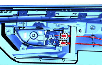
Connect the front door lock remote control cable assembly LH and front door inside locking cable assembly LH.
-
Attach the 2 clamps.
-
for Driver Side with Memory:
-
Disconnect the connector.
-
-
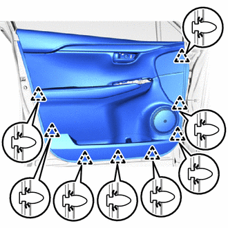
Attach the 8 clips to install the front door trim board sub-assembly LH.
-
Screw A Screw B 
Screw C Install the screw labeled A.
-
Install the screw labeled B.
-
Install the screw labeled C.
-
-
INSTALL POWER WINDOW REGULATOR MASTER SWITCH ASSEMBLY WITH FRONT DOOR ARMREST BASE PANEL (for Driver Side)
-
Connect the 2 connectors.
-
Attach the 4 claws, 2 clips to install the power window regulator master switch assembly with front door armrest base panel.
-
-
INSTALL POWER WINDOW REGULATOR SWITCH ASSEMBLY WITH FRONT DOOR ARMREST BASE PANEL (for Front Passenger Side)
-
Connect the 2 connectors.
-
Attach the 4 claws, 2 clips to install the power window regulator switch assembly with front door armrest base panel.
-
-
INSTALL FRONT DOOR INSIDE HANDLE BEZEL PLUG LH
-
Attach the 3 claws to install the front door inside handle bezel plug LH.
-
-
INSTALL FRONT DOOR TRIM COVER LH
-
Install the front door trim cover LH.
-
-
CONNECT CABLE TO NEGATIVE AUXILIARY BATTERY TERMINAL
Note
When disconnecting the cable, some systems need to be initialized after the cable is reconnected.
-
w/o Spare Tire:
Detach the 2 claws and remove the battery service cover.
-
Tighten the nut and connect the cable from to auxiliary battery negative (-) terminal.
- Torque:
- 5.4 N*m { 55 kgf*cm, 48 in.*lbf }
-
-
INSTALL DECK FLOOR BOX LH (w/ Spare Tire)
-
INSTALL REAR DECK FLOOR BOX (w/ Spare Tire)
-
INSTALL NO. 3 DECK BOARD SUB-ASSEMBLY (w/ Spare Tire)
-
PERFORM DIAGNOSTIC SYSTEM CHECK
-
CHECK SRS WARNING LIGHT
-
INITIALIZE POWER WINDOW CONTROL SYSTEM
-
CHECK POWER WINDOW CONTROL SYSTEM
-
INSPECT FRONT POWER SEAT CONTROL SYSTEM (for Driver Side with Memory)
-
CHECK POWER DOOR LOCK CONTROL SYSTEM