POWER BACK DOOR SYSTEM Power Back Door cannot be Opened or Closed Using the Power Back Door Switch
DESCRIPTION
When the power back door cannot be opened or closed using the combination switch assembly, one of the following may be malfunctioning: 1) combination switch assembly circuit, 2) multiplex network door ECU or 3) main body ECU (multiplex network body ECU).
WIRING DIAGRAM
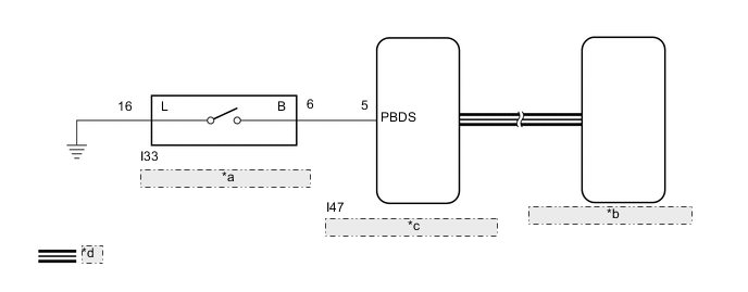
| *a | Combination Switch Assembly |
| *b | Multiplex Network Door ECU |
| *c | Main Body ECU (Multiplex Network Body ECU) |
| *d | CAN Communication Line |
CAUTION / NOTICE / HINT
Note
-
First perform the communication function inspections in How to Proceed with Troubleshooting to confirm that there are no CAN communication malfunctions before troubleshooting this problem.
-
If the replacement, removal and installation of the multiplex network door ECU or disconnection of the connectors of the multiplex network door ECU has been performed, initialize the power back door system.
-
If the main body ECU (multiplex network body ECU) is replaced, refer to Service Bulletin.
PROCEDURE
-
READ VALUE USING GTS
-
Read the Data List according to the display on the GTS.
Body Electrical > Main Body > Data ListTester Display Measurement Item Range Normal Condition Diagnostic Note Back Door Open SW Combination switch assembly signal ON or OFF ON: Combination switch assembly pushed
OFF: Combination switch assembly not pushed
-
Body Electrical > Main Body > Data ListTester Display Back Door Open SW OK The combination switch assembly functions as specified in the normal condition column. Result Proceed to OK NG
NG 
INSPECT COMBINATION SWITCH ASSEMBLY Click here
OK 
-
-
REPLACE MULTIPLEX NETWORK DOOR ECU
-
Temporarily replace the multiplex network door ECU with a new or normally functioning one.
Result Proceed to NEXT
NEXT
-
-
INITIALIZE MULTIPLEX NETWORK DOOR ECU
-
Perform the initialization for the multiplex network door ECU.
Result Proceed to NEXT
NEXT
-
-
CHECK BACK DOOR CLOSER SYSTEM
-
Check that the power back door operates normally.
OK Power back door operates normally Result Result Proceed to OK A NG (for LHD) B NG (for RHD) C
A 
END (MULTIPLEX NETWORK DOOR ECU WAS DEFECTIVE)
B
REPLACE MAIN BODY ECU (MULTIPLEX NETWORK BODY ECU) Click here
C
REPLACE MAIN BODY ECU (MULTIPLEX NETWORK BODY ECU) Click here
-
-
INSPECT COMBINATION SWITCH ASSEMBLY
-
Remove the combination switch assembly.
-
Inspect the combination switch assembly.
Result Proceed to OK NG
NG
REPLACE COMBINATION SWITCH ASSEMBLY Click here
OK
-
-
CHECK HARNESS AND CONNECTOR (COMBINATION SWITCH ASSEMBLY - MAIN BODY ECU [MULTIPLEX NETWORK BODY ECU] AND BODY GROUND)
-
Disconnect the I33 combination switch assembly connector.
-
Disconnect the I47 main body ECU (multiplex network body ECU) connector.
-
Measure the resistance according to the value(s) in the table below.
Standard Resistance Tester Connection Condition Specified Condition I33-6 (B) - I47-5 (PBDS) Always Below 1 Ω I33-16 (L) - Body ground Always Below 1 Ω I33-6 (B) or I47-5 (PBDS) - Body ground Always 10 kΩ or higher Result Result Proceed to OK (for LHD) A OK (for RHD) B NG C
A
REPLACE MAIN BODY ECU (MULTIPLEX NETWORK BODY ECU) Click here
B
REPLACE MAIN BODY ECU (MULTIPLEX NETWORK BODY ECU) Click here
C
REPAIR OR REPLACE HARNESS OR CONNECTOR
-