BACK DOOR CLOSER SYSTEM TERMINALS OF ECU
-
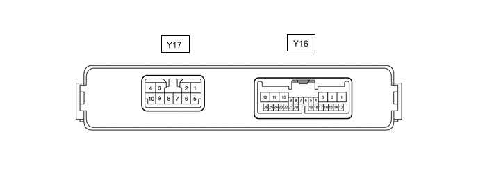
CHECK MULTIPLEX NETWORK DOOR ECU
-
Disconnect the Y16 and Y17 multiplex network door ECU connectors.
-
Measure the voltage and resistance according to the value(s) in the table below.
Tech Tips
Measure the values on the wire harness side with the connector disconnected.
Terminal No. (Symbol) Wiring Color Terminal Description Condition Specified Condition Y16-1 (ECUB) - Body ground W - Body ground Auxiliary battery power supply Power switch off 11 to 14 V Y16-7 (IG) - Body ground W - Body ground IG power supply Power switch on (IG) 11 to 14 V Power switch off Below 1 V Y17-8 (B) - Body ground LA-W - Body ground Auxiliary battery power supply Power switch off 11 to 14 V Y17-7 (GND) - Body ground W-B - Body ground Body ground Always Below 1 Ω -
Reconnect the Y16 and Y17 multiplex network door ECU connectors.
-
Measure the voltage and waveform according to the value(s) in the table below.
Terminal No. (Symbol) Wiring Color Terminal Description Condition Specified Condition Y17-10 (DC+) - Y17-9 (DC-) LA-R - LA-BR Back door lock assembly (back door lock motor) circuit Back door lock motor operating 11 to 14 V Back door lock motor not operating Below 1 V Y16-19 (FUL) - Body ground W - Body ground Back door lock assembly (back door courtesy light switch) signal circuit Back door closed → open Pulse generation → Below 1 V Y16-21 (HAF) - Body ground G - Body ground Back door lock assembly (latch switch) signal circuit Back door closed → fully open 11 to 14 V → Below 1 V Y16-24 (POS) - Body ground B - Body ground Back door lock assembly (initial switch) signal circuit Back door open → Back door closer operates → Back door closed Below 1 V → 11 to 14 V → Below 1 V
-
-
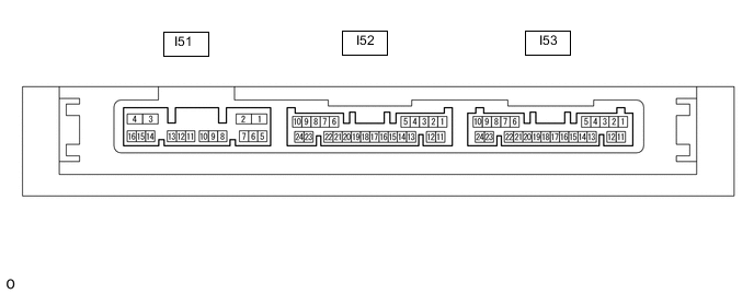
CHECK CERTIFICATION ECU (SMART KEY ECU ASSEMBLY)
-
Disconnect the I53 certification ECU (smart key ECU assembly) connector.
-
Measure the voltage and resistance according to the value(s) in the table below.
Tech Tips
Measure the values on the wire harness side with the connector disconnected.
Terminal No. (Symbol) Wiring Color Terminal Description Condition Specified Condition I53-10 (+B) - Body ground W - Body ground Auxiliary battery power supply Power switch off 11 to 14 V I53-11 (E) - Body ground W-B - Body ground Body ground Always Below 1 Ω -
Reconnect the I53 certification ECU (smart key ECU assembly) connector.
-
Measure the voltage and waveform according to the value(s) in the table below.
Terminal No. (Symbol) Wiring Color Terminal Description Condition Specified Condition I52-5 (TSW5) - Body ground Y - Body ground Back door opener switch assembly signal Back door opener switch assembly (open switch) off Pulse generation Back door opener switch assembly (open switch) on Below 1 V
-