HEATED WINDSHIELD DEFROSTER SYSTEM TERMINALS OF ECU
-
CHECK AIR CONDITIONING AMPLIFIER ASSEMBLY
-
Disconnect the I50 air conditioning amplifier assembly connector.
-
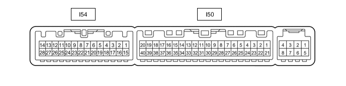
Measure the voltage and resistance according to the value(s) in the table below.
Terminal No. (Symbol) Wiring Color Terminal Description Condition Specified Condition I50-1 (IG+) - I50-14 (GND) SB - W-B IG power source Power switch on (IG) 11 to 14 V Power switch off Below 1 V I50-21 (B) - I50-14 (GND) GR - W-B Auxiliary battery power source Power switch off 11 to 14 V I50-14 (GND) - Body ground W-B - Body ground Body ground Always Below 1 Ω -
Reconnect the I50 air conditioning amplifier assembly connector.
-
Measure the voltage according to the value(s) in the table below.
Terminal No. (Symbol) Wiring Color Terminal Description Condition Specified Condition I50-39 (FDEF) - I50-14 (GND) L - W-B EHW NO. 1 relay signal Power switch on (IG), No. 2 combination switch assembly (windshield deicer switch) off 11 to 14 V Power switch on (IG), No. 2 combination switch assembly (windshield deicer switch) on Below 2.2 V I54-21 (DFAC) - I50-14 (GND) L - W-B No. 2 combination switch assembly (windshield deicer switch) input Power switch on (IG), No. 2 combination switch assembly (windshield deicer switch) off Below 1 V Power switch on (IG), No. 2 combination switch assembly (windshield deicer switch) on 11 to 14 V I50-23 (IND) - I50-14 (GND) R - W-B No. 2 combination switch assembly (windshield deicer switch) indicator output Power switch on (IG), No. 2 combination switch assembly (windshield deicer switch) off 11 to 14 V Power switch on (IG), No. 2 combination switch assembly (windshield deicer switch) on Below 1 V
-