ROOF HEADLINING REASSEMBLY

CAUTION / NOTICE / HINT
Tech Tips
-
Use the same procedure for RHD and LHD vehicles.
-
The procedure listed below is for LHD vehicles.
PROCEDURE
-
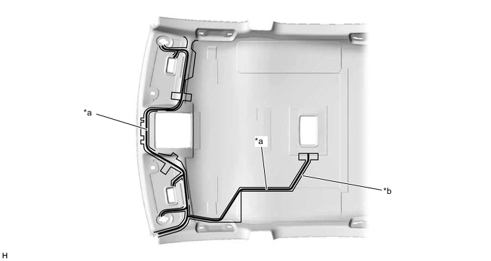
INSTALL NO. 2 ANTENNA CORD SUB-ASSEMBLY
-
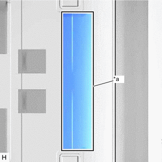
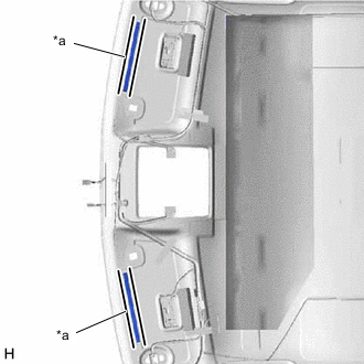
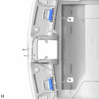
INSTALL NO. 4 ROOF HEADLINING SUPPORT (for Normal Roof, for Type B)
-
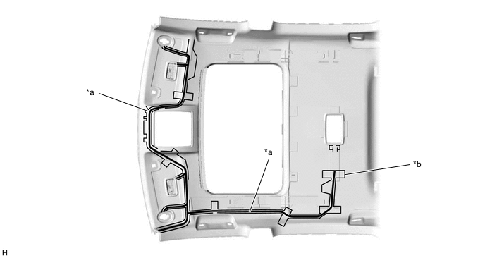
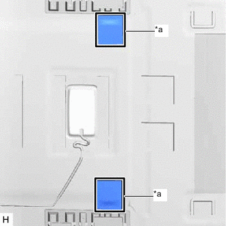
*a Marking Align the No. 4 roof headlining support with the marking on the roof headlining and install the No. 4 roof headlining support using double-sided tape or hot-melt glue as shown in the illustration.
-
-
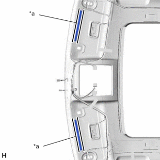
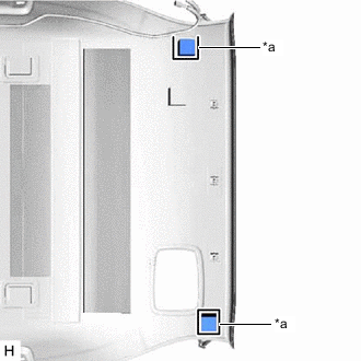
INSTALL NO. 3 ROOF HEADLINING SUPPORT (for Normal Roof, for Type B)
-
*a Marking Align the No. 3 roof headlining support with the marking on the roof headlining and install the No. 3 roof headlining support using double-sided tape or hot-melt glue as shown in the illustration.
-
-
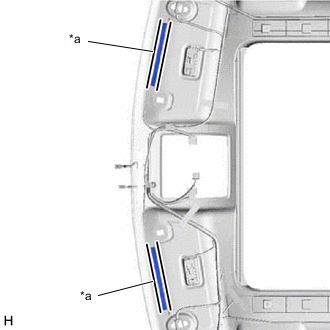
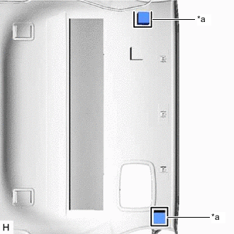
INSTALL NO. 4 ROOF HEADLINING SUPPORT (for Sliding Roof, for Type B)
-
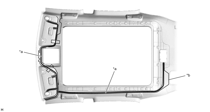
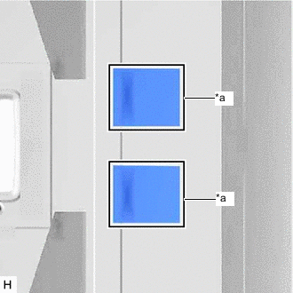
*a Marking Align the No. 4 roof headlining support with the marking on the roof headlining and install the No. 4 roof headlining support using double-sided tape or hot-melt glue as shown in the illustration.
-
-
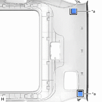
INSTALL NO. 3 ROOF HEADLINING SUPPORT (for Sliding Roof, for Type B)
-
*a Marking Align the No. 3 roof headlining support with the marking on the roof headlining and install the No. 3 roof headlining support using double-sided tape or hot-melt glue as shown in the illustration.
-
-
INSTALL NO. 1 ROOF WIRE (for Normal Roof)
-
for LHD:
-
Apply butyl tape as shown in the illustration.
Tech Tips
Place the tape securely so that it is not misaligned or peeling.
*a Butyl Tape *b Marking -
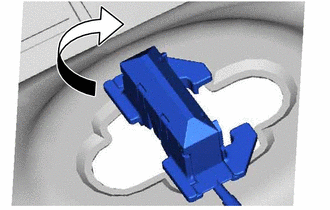
Turn the visor connectors approximately 90° clockwise to install them to the roof headlining.
-
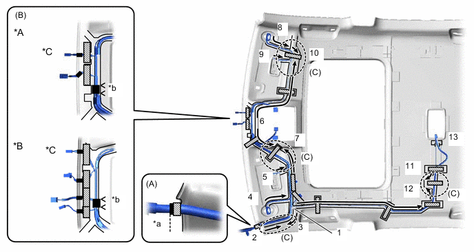
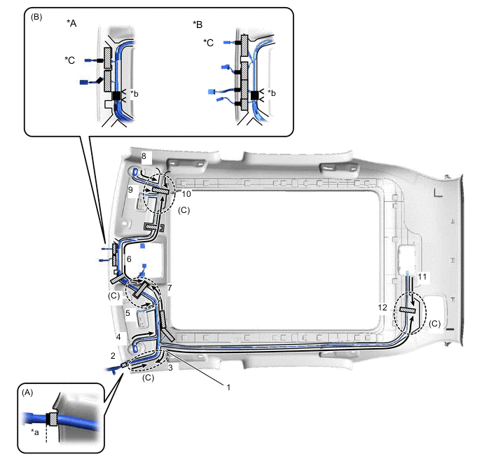
Attach the No. 1 roof wire to the butyl tape in the order and direction indicated by the arrows shown in the illustration and secure the No. 1 roof wire with pieces of fastening tape.
Tech Tips
-
Align the positioning tape of the No. 1 roof wire with the protrusion of the roof headlining and wrap a piece of fastening tape around the No. 1 roof wire and protrusion as shown in the part of the illustration labeled (A).
-
Secure the No. 1 roof wire so that the positioning tape does not protrude from the cutout of the roof headlining as shown in the part of the illustration labeled (B).
-
Secure the No. 1 roof wire so that the No. 1 roof wire is between the roof headlining V marks as shown in the part of the illustration labeled (B).
-
Adjust the slack of the No. 1 roof wire as shown in the parts of the illustration labeled (C).
-
Make sure that the No. 1 roof wire is securely attached to the roof headlining along its entire length and not twisted.
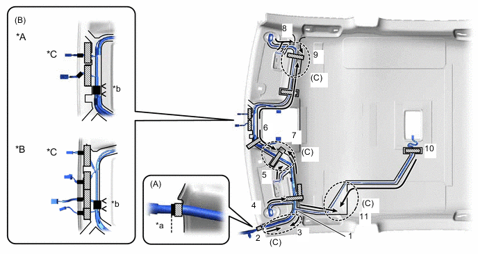
*A w/o Lane Departure Alert System *B w/ Lane Departure Alert System *C w/ Rain Sensor - - *a Align positioning tape of No. 1 roof wire and protrusion of roof headlining *b V Mark 
Fastening Tape 
Positioning Tape -
-
-
for RHD:
-
Apply butyl tape as shown in the illustration.
Tech Tips
Place the tape securely so that it is not misaligned or peeling.

*a Butyl Tape *b Marking -
Turn the visor connectors approximately 90° clockwise to install them to the roof headlining.
-
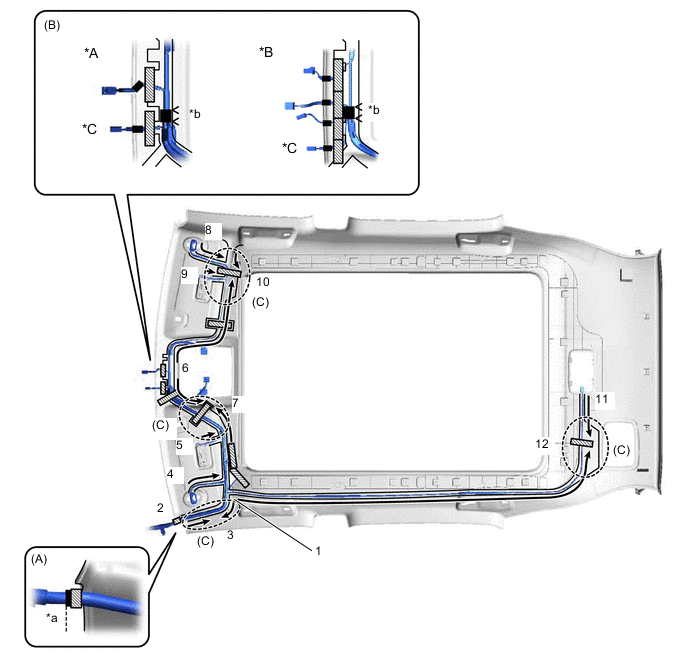
Attach the No. 1 roof wire to the butyl tape in the order and direction indicated by the arrows shown in the illustration and secure the No. 1 roof wire with pieces of fastening tape.
Tech Tips
-
Align the positioning tape of the No. 1 roof wire with the protrusion of the roof headlining and wrap a piece of fastening tape around the No. 1 roof wire and protrusion as shown in the part of the illustration labeled (A).
-
Secure the No. 1 roof wire so that the positioning tape does not protrude from the cutout of the roof headlining as shown in the part of the illustration labeled (B).
-
Secure the No. 1 roof wire so that the No. 1 roof wire is between the roof headlining V marks as shown in the part of the illustration labeled (B).
-
Adjust the slack of the No. 1 roof wire as shown in the parts of the illustration labeled (C).
-
Make sure that the No. 1 roof wire is securely attached to the roof headlining along its entire length and not twisted.
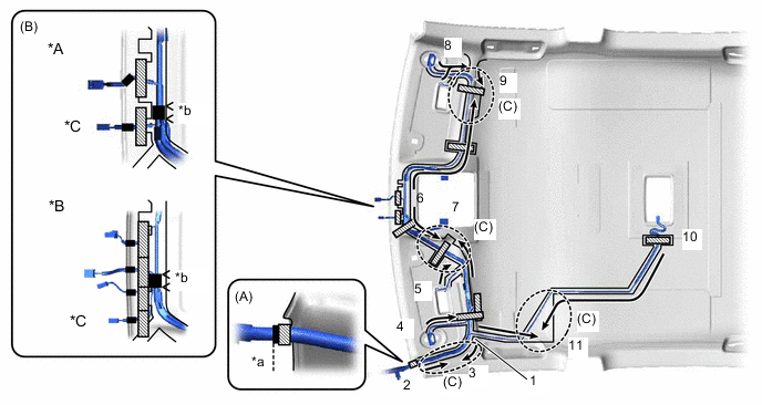
*A w/o Lane Departure Alert System *B w/ Lane Departure Alert System *C w/ Rain Sensor - - *a Align positioning tape of No. 1 roof wire and protrusion of roof headlining *b V Mark Fastening Tape Positioning Tape -
-
-
-
INSTALL NO. 1 ROOF WIRE (for Sliding Roof)
-
for LHD:
-
Apply butyl tape as shown in the illustration.
Tech Tips
Place the tape securely so that it is not misaligned or peeling.

*a Butyl Tape *b Marking -
Turn the visor connectors approximately 90° clockwise to install them to the roof headlining.
-
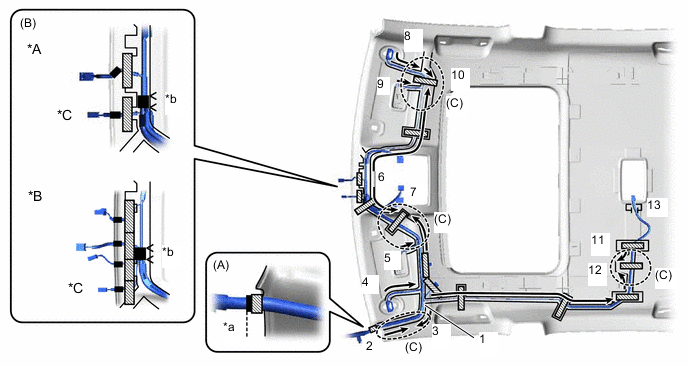
Attach the No. 1 roof wire to the butyl tape in the order and direction indicated by the arrows shown in the illustration and secure the No. 1 roof wire with pieces of fastening tape.
Tech Tips
-
Align the positioning tape of the No. 1 roof wire with the protrusion of the roof headlining and wrap a piece of fastening tape around the No. 1 roof wire and protrusion as shown in the part of the illustration labeled (A).
-
Secure the No. 1 roof wire so that the positioning tape does not protrude from the cutout of the roof headlining as shown in the part of the illustration labeled (B).
-
Secure the No. 1 roof wire so that the No. 1 roof wire is between the roof headlining V marks as shown in the part of the illustration labeled (B).
-
Adjust the slack of the No. 1 roof wire as shown in the parts of the illustration labeled (C).
-
Make sure that the No. 1 roof wire is securely attached to the roof headlining along its entire length and not twisted.
*A w/o Lane Departure Alert System *B w/ Lane Departure Alert System *C w/ Rain Sensor - - *a Align positioning tape of No. 1 roof wire and protrusion of roof headlining *b V Mark Fastening Tape Positioning Tape -
-
-
for RHD:
-
Apply butyl tape as shown in the illustration.
Tech Tips
Place the tape securely so that it is not misaligned or peeling.
*a Butyl Tape *b Marking -
Turn the visor connectors approximately 90° clockwise to install them to the roof headlining.
-
Attach the No. 1 roof wire to the butyl tape in the order and direction indicated by the arrows shown in the illustration and secure the No. 1 roof wire with pieces of fastening tape.
Tech Tips
-
Align the positioning tape of the No. 1 roof wire with the protrusion of the roof headlining and wrap a piece of fastening tape around the No. 1 roof wire and protrusion as shown in the part of the illustration labeled (A).
-
Secure the No. 1 roof wire so that the positioning tape does not protrude from the cutout of the roof headlining as shown in the part of the illustration labeled (B).
-
Secure the No. 1 roof wire so that the No. 1 roof wire is between the roof headlining V marks as shown in the part of the illustration labeled (B).
-
Adjust the slack of the No. 1 roof wire as shown in the parts of the illustration labeled (C).
-
Make sure that the No. 1 roof wire is securely attached to the roof headlining along its entire length and not twisted.
*A w/o Lane Departure Alert System *B w/ Lane Departure Alert System *C w/ Rain Sensor - - *a Align positioning tape of No. 1 roof wire and protrusion of roof headlining *b V Mark Fastening Tape Positioning Tape -
-
-
-
INSTALL NO. 1 ROOF WIRE (for Glass Roof)
-
for LHD:
-
Apply butyl tape as shown in the illustration.
Tech Tips
Place the tape securely so that it is not misaligned or peeling.
*a Butyl Tape *b Marking -
Turn the visor connectors approximately 90° clockwise to install them to the roof headlining.
-
Attach the No. 1 roof wire to the butyl tape in the order and direction indicated by the arrows shown in the illustration and secure the No. 1 roof wire with pieces of fastening tape.
Tech Tips
-
Align the positioning tape of the No. 1 roof wire with the protrusion of the roof headlining and wrap a piece of fastening tape around the No. 1 roof wire and protrusion as shown in the part of the illustration labeled (A).
-
Secure the No. 1 roof wire so that the positioning tape does not protrude from the cutout of the roof headlining as shown in the part of the illustration labeled (B).
-
Secure the No. 1 roof wire so that the No. 1 roof wire is between the roof headlining V marks as shown in the part of the illustration labeled (B).
-
Adjust the slack of the No. 1 roof wire as shown in the parts of the illustration labeled (C).
-
Make sure that the No. 1 roof wire is securely attached to the roof headlining along its entire length and not twisted.
*A w/o Lane Departure Alert System *B w/ Lane Departure Alert System *C w/ Rain Sensor - - *a Align positioning tape of No. 1 roof wire and protrusion of roof headlining *b V Mark Fastening Tape Positioning Tape -
-
-
for RHD:
-
Apply butyl tape as shown in the illustration.
Tech Tips
Place the tape securely so that it is not misaligned or peeling.

*a Butyl Tape *b Marking -
Turn the visor connectors approximately 90° clockwise to install them to the roof headlining.
-
Attach the No. 1 roof wire to the butyl tape in the order and direction indicated by the arrows shown in the illustration and secure the No. 1 roof wire with pieces of fastening tape.
Tech Tips
-
Align the positioning tape of the No. 1 roof wire with the protrusion of the roof headlining and wrap a piece of fastening tape around the No. 1 roof wire and protrusion as shown in the part of the illustration labeled (A).
-
Secure the No. 1 roof wire so that the positioning tape does not protrude from the cutout of the roof headlining as shown in the part of the illustration labeled (B).
-
Secure the No. 1 roof wire so that the No. 1 roof wire is between the roof headlining V marks as shown in the part of the illustration labeled (B).
-
Adjust the slack of the No. 1 roof wire as shown in the parts of the illustration labeled (C).
-
Make sure that the No. 1 roof wire is securely attached to the roof headlining along its entire length and not twisted.
*A w/o Lane Departure Alert System *B w/ Lane Departure Alert System *C w/ Rain Sensor - - *a Align positioning tape of No. 1 roof wire and protrusion of roof headlining *b V Mark Fastening Tape Positioning Tape -
-
-
-
INSTALL NO. 1 ROOF SILENCER PAD (for Normal Roof)
-
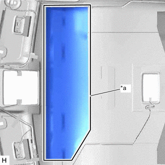
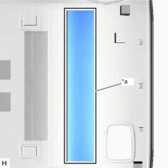
*a Silencer Marking Align the No. 1 roof silencer pad with the silencer marking on the roof headlining and install the No. 1 roof silencer pad using double-sided tape or hot-melt glue as shown in the illustration.
-
-
INSTALL NO. 2 ROOF SILENCER PAD (for Normal Roof)
-
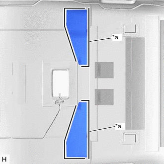
*a Silencer Marking for Type A:
Align the No. 2 roof silencer pads with the silencer markings on the roof headlining and install the 2 No. 2 roof silencer pads using double-sided tape or hot-melt glue as shown in the illustration.
-
*a Silencer Marking for Type B:
Align the No. 2 roof silencer pads with the silencer markings on the roof headlining and install the 2 No. 2 roof silencer pads using double-sided tape or hot-melt glue as shown in the illustration.
-
-
INSTALL NO. 3 ROOF SILENCER PAD (for Normal Roof)
-
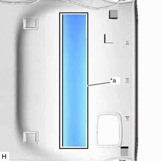
*a Silencer Marking Align the No. 3 roof silencer pads with the silencer markings on the roof headlining and install the 2 No. 3 roof silencer pads using double-sided tape or hot-melt glue as shown in the illustration.
-
-
INSTALL REAR ROOF SILENCER PAD (for Normal Roof)
-
*a Silencer Marking Align the rear roof silencer pad with the silencer marking on the roof headlining and install the rear roof silencer pad using double-sided tape or hot-melt glue as shown in the illustration.
-
-
INSTALL REAR ROOF SILENCER PAD (for Sliding Roof)
-
*a Silencer Marking Align the rear roof silencer pad with the silencer marking on the roof headlining and install the rear roof silencer pad using double-sided tape or hot-melt glue as shown in the illustration.
-
-
INSTALL NO. 4 ROOF SILENCER PAD (for Normal Roof)
-
*a Silencer Marking Align the No. 4 roof silencer pad with the silencer marking on the roof headlining and install the No. 4 roof silencer pad using double-sided tape or hot-melt glue as shown in the illustration.
-
-
INSTALL ROOF HEADLINING PAD (for Normal Roof)
-
*a Silencer Marking Align the roof headlining pads with the silencer markings on the roof headlining and install the 2 roof headlining pads using double-sided tape or hot-melt glue as shown in the illustration.
-
-
INSTALL ROOF HEADLINING PAD (for Sliding Roof)
-
*a Silencer Marking Align the roof headlining pads with the silencer markings on the roof headlining and install the 2 roof headlining pads using double-sided tape or hot-melt glue as shown in the illustration.
-
-
INSTALL ROOF HEADLINING PAD (for Glass Roof)
-
*a Silencer Marking Align the roof headlining pads with the silencer markings on the roof headlining and install the 2 roof headlining pads using double-sided tape or hot-melt glue as shown in the illustration.
-
-
INSTALL FRONT ROOF HEADLINING SIDE PAD (for Normal Roof)
-
*a Silencer Marking Align the front roof headlining side pads with the silencer markings on the roof headlining and install the 2 front roof headlining side pads using double-sided tape or hot-melt glue as shown in the illustration.
-
-
INSTALL ROOF HEADLINING END PAD (for Normal Roof)
-
*a Silencer Marking Align the roof headlining end pads with the silencer markings on the roof headlining and install the 2 roof headlining end pads using double-sided tape or hot-melt glue as shown in the illustration.
-
-
INSTALL ROOF HEADLINING END PAD (for Sliding Roof)
-
*a Silencer Marking Align the roof headlining end pads with the silencer markings on the roof headlining and install the 2 roof headlining end pads using double-sided tape or hot-melt glue as shown in the illustration.
-
-
INSTALL ROOF HEADLINING END PAD (for Glass Roof)
-
*a Silencer Marking Align the roof headlining end pads with the silencer markings on the roof headlining and install the 2 roof headlining end pads using double-sided tape or hot-melt glue as shown in the illustration.
-
-
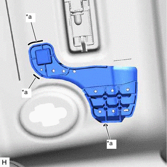
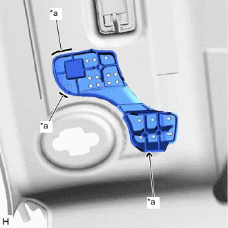
INSTALL NO. 2 ROOF HEADLINING SUPPORT (for Normal Roof, for Type B)
-
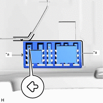
*a Marking Align the No. 2 roof headlining support with the marking on the roof headlining and install the No. 2 roof headlining support using double-sided tape or hot-melt glue as shown in the illustration.
Tech Tips
Make sure to install the support facing the front of the vehicle in the direction of the arrow shown in the illustration.
-
-
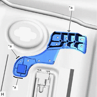
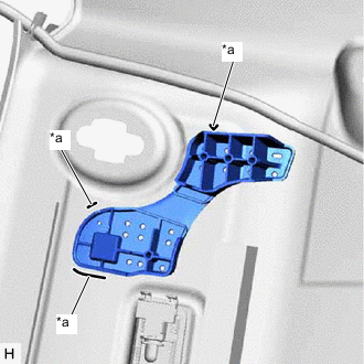
INSTALL ROOF HEADLINING SUPPORT (for Normal Roof, for Type B)
-
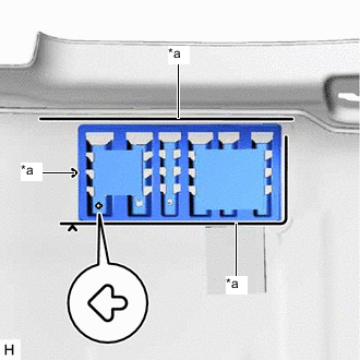
*a Marking Align the roof headlining support with the marking on the roof headlining and install the roof headlining support using double-sided tape or hot-melt glue as shown in the illustration.
Tech Tips
Make sure to install the support facing the front of the vehicle in the direction of the arrow shown in the illustration.
-
-
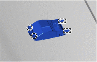
INSTALL NO. 1 MICROPHONE CASE
-
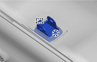
Attach the guide and claw to install the No. 1 microphone case.
-
-
INSTALL TELEPHONE MICROPHONE ASSEMBLY
-
INSTALL VANITY LIGHT ASSEMBLY
Tech Tips
Use the same procedure for both vanity light assemblies.
-
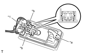
*1 Bulb Holder *a Claw A *b Claw B Attach claw A of the vanity light assembly to temporarily install the vanity light assembly to the roof headlining.
-
Attach the 2 claws B of the bulb holder to install the vanity light assembly.
-
-
INSTALL CHILD RESTRAINT SEAT TETHER ANCHOR COVER (for Type B)
-
Attach the 2 guides and 2 claws to install the child restraint seat tether anchor cover.
-