ROOF HEADLINING REASSEMBLY

CAUTION / NOTICE / HINT
Tech Tips
-
Use the same procedure for RHD and LHD vehicles.
-
The procedure listed below is for LHD vehicles.
PROCEDURE
-
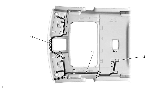
INSTALL NO. 2 ANTENNA CORD SUB-ASSEMBLY
-
INSTALL NO. 1 ROOF WIRE (for Normal Roof)
-
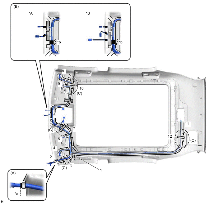
for LHD:
-
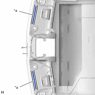
Apply butyl tape as shown in the illustration.
Tech Tips
Place the tape securely so that it is not misaligned or peeling.
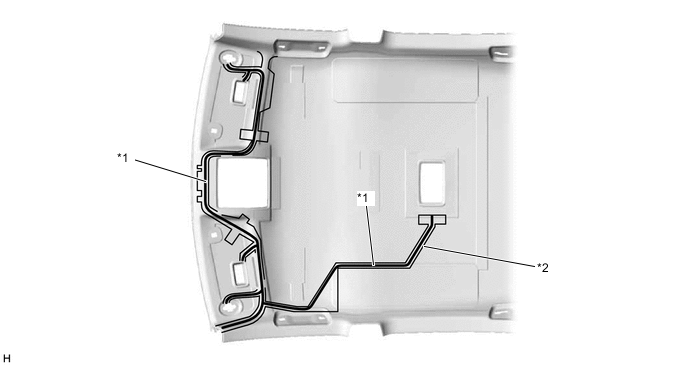
*1 Butyl Tape *2 Marking -
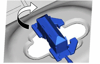
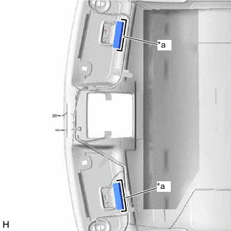
Turn the visor connectors approximately 90° clockwise to install them to the roof headlining.
-
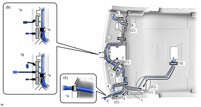
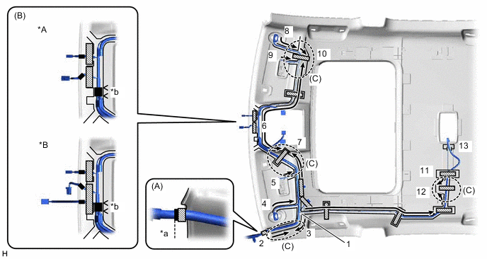
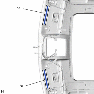
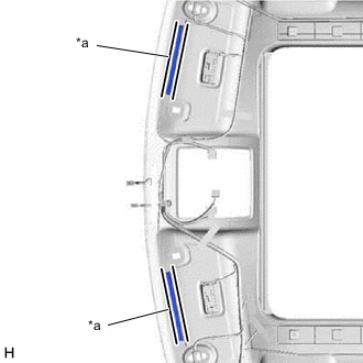
Attach the No. 1 roof wire to the butyl tape in the order and direction indicated by the arrows shown in the illustration and secure the No. 1 roof wire with pieces of fastening tape.
Tech Tips
-
Align the positioning tape of the No. 1 roof wire with the protrusion of the roof headlining and wrap a piece of fastening tape around the No. 1 roof wire and protrusion as shown in the part of the illustration labeled (A).
-
Secure the No. 1 roof wire so that the positioning tape does not protrude from the cutout of the roof headlining as shown in the part of the illustration labeled (B).
-
Secure the No. 1 roof wire so that the No. 1 roof wire is between the roof headlining V marks as shown in the part of the illustration labeled (B).
-
Adjust the slack of the No. 1 roof wire as shown in the parts of the illustration labeled (C).
-
Make sure that the No. 1 roof wire is securely attached to the roof headlining along its entire length and not twisted.
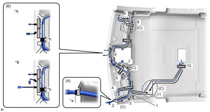
*A w/o Lane Departure Alert System *B w/ Lane Departure Alert System *a Align positioning tape of No. 1 roof wire and protrusion of roof headlining *b V Mark 
Fastening Tape 
Positioning Tape -
-
-
for RHD:
-
Apply butyl tape as shown in the illustration.
Tech Tips
Place the tape securely so that it is not misaligned or peeling.
*1 Butyl Tape *2 Marking -
Turn the visor connectors approximately 90° clockwise to install them to the roof headlining.
-
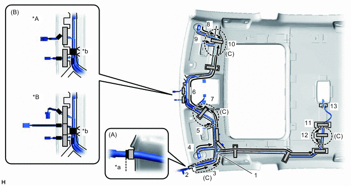
Attach the No. 1 roof wire to the butyl tape in the order and direction indicated by the arrows shown in the illustration and secure the No. 1 roof wire with pieces of fastening tape.
Tech Tips
-
Align the positioning tape of the No. 1 roof wire with the protrusion of the roof headlining and wrap a piece of fastening tape around the No. 1 roof wire and protrusion as shown in the part of the illustration labeled (A).
-
Secure the No. 1 roof wire so that the positioning tape does not protrude from the cutout of the roof headlining as shown in the part of the illustration labeled (B).
-
Secure the No. 1 roof wire so that the No. 1 roof wire is between the roof headlining V marks as shown in the part of the illustration labeled (B).
-
Adjust the slack of the No. 1 roof wire as shown in the parts of the illustration labeled (C).
-
Make sure that the No. 1 roof wire is securely attached to the roof headlining along its entire length and not twisted.
*A w/o Lane Departure Alert System *B w/ Lane Departure Alert System *a Align positioning tape of No. 1 roof wire and protrusion of roof headlining *b V Mark Fastening Tape Positioning Tape -
-
-
-
INSTALL NO. 1 ROOF WIRE (for Sliding Roof)
-
for LHD:
-
Apply butyl tape as shown in the illustration.
Tech Tips
Place the tape securely so that it is not misaligned or peeling.
*1 Butyl Tape *2 Marking -
Turn the visor connectors approximately 90° clockwise to install them to the roof headlining.
-
Attach the No. 1 roof wire to the butyl tape in the order and direction indicated by the arrows shown in the illustration and secure the No. 1 roof wire with pieces of fastening tape.
Tech Tips
-
Align the positioning tape of the No. 1 roof wire with the protrusion of the roof headlining and wrap a piece of fastening tape around the No. 1 roof wire and protrusion as shown in the part of the illustration labeled (A).
-
Secure the No. 1 roof wire so that the positioning tape does not protrude from the cutout of the roof headlining as shown in the part of the illustration labeled (B).
-
Secure the No. 1 roof wire so that the No. 1 roof wire is between the roof headlining V marks as shown in the part of the illustration labeled (B).
-
Adjust the slack of the No. 1 roof wire as shown in the parts of the illustration labeled (C).
-
Make sure that the No. 1 roof wire is securely attached to the roof headlining along its entire length and not twisted.
*A w/o Lane Departure Alert System *B w/ Lane Departure Alert System *a Align positioning tape of No. 1 roof wire and protrusion of roof headlining *b V Mark Fastening Tape Positioning Tape -
-
-
for RHD:
-
Apply butyl tape as shown in the illustration.
Tech Tips
Place the tape securely so that it is not misaligned or peeling.
*1 Butyl Tape *2 Marking -
Turn the visor connectors approximately 90° clockwise to install them to the roof headlining.
-
Attach the No. 1 roof wire to the butyl tape in the order and direction indicated by the arrows shown in the illustration and secure the No. 1 roof wire with pieces of fastening tape.
Tech Tips
-
Align the positioning tape of the No. 1 roof wire with the protrusion of the roof headlining and wrap a piece of fastening tape around the No. 1 roof wire and protrusion as shown in the part of the illustration labeled (A).
-
Secure the No. 1 roof wire so that the positioning tape does not protrude from the cutout of the roof headlining as shown in the part of the illustration labeled (B).
-
Secure the No. 1 roof wire so that the No. 1 roof wire is between the roof headlining V marks as shown in the part of the illustration labeled (B).
-
Adjust the slack of the No. 1 roof wire as shown in the parts of the illustration labeled (C).
-
Make sure that the No. 1 roof wire is securely attached to the roof headlining along its entire length and not twisted.
*A w/o Lane Departure Alert System *B w/ Lane Departure Alert System *a Align positioning tape of No. 1 roof wire and protrusion of roof headlining *b V Mark Fastening Tape Positioning Tape -
-
-
-
INSTALL NO. 1 ROOF WIRE (for Glass Roof)
-
for LHD:
-
Apply butyl tape as shown in the illustration.
Tech Tips
Place the tape securely so that it is not misaligned or peeling.
*1 Butyl Tape *2 Marking -
Turn the visor connectors approximately 90° clockwise to install them to the roof headlining.
-
Attach the No. 1 roof wire to the butyl tape in the order and direction indicated by the arrows shown in the illustration and secure the No. 1 roof wire with pieces of fastening tape.
Tech Tips
-
Align the positioning tape of the No. 1 roof wire with the protrusion of the roof headlining and wrap a piece of fastening tape around the No. 1 roof wire and protrusion as shown in the part of the illustration labeled (A).
-
Secure the No. 1 roof wire so that the positioning tape does not protrude from the cutout of the roof headlining as shown in the part of the illustration labeled (B).
-
Secure the No. 1 roof wire so that the No. 1 roof wire is between the roof headlining V marks as shown in the part of the illustration labeled (B).
-
Adjust the slack of the No. 1 roof wire as shown in the parts of the illustration labeled (C).
-
Make sure that the No. 1 roof wire is securely attached to the roof headlining along its entire length and not twisted.
*A w/o Lane Departure Alert System *B w/ Lane Departure Alert System *a Align positioning tape of No. 1 roof wire and protrusion of roof headlining *b V Mark Fastening Tape Positioning Tape -
-
-
for RHD:
-
Apply butyl tape as shown in the illustration.
Tech Tips
Place the tape securely so that it is not misaligned or peeling.
*1 Butyl Tape *2 Marking -
Turn the visor connectors approximately 90° clockwise to install them to the roof headlining.
-
Attach the No. 1 roof wire to the butyl tape in the order and direction indicated by the arrows shown in the illustration and secure the No. 1 roof wire with pieces of fastening tape.
Tech Tips
-
Align the positioning tape of the No. 1 roof wire with the protrusion of the roof headlining and wrap a piece of fastening tape around the No. 1 roof wire and protrusion as shown in the part of the illustration labeled (A).
-
Secure the No. 1 roof wire so that the positioning tape does not protrude from the cutout of the roof headlining as shown in the part of the illustration labeled (B).
-
Secure the No. 1 roof wire so that the No. 1 roof wire is between the roof headlining V marks as shown in the part of the illustration labeled (B).
-
Adjust the slack of the No. 1 roof wire as shown in the parts of the illustration labeled (C).
-
Make sure that the No. 1 roof wire is securely attached to the roof headlining along its entire length and not twisted.
*A w/o Lane Departure Alert System *B w/ Lane Departure Alert System *a Align positioning tape of No. 1 roof wire and protrusion of roof headlining *b V Mark Fastening Tape Positioning Tape -
-
-
-
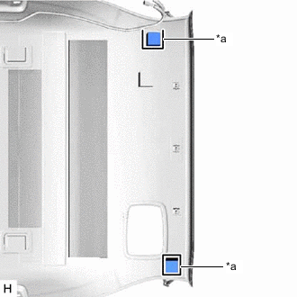
INSTALL NO. 1 ROOF SILENCER PAD (for Normal Roof)
-
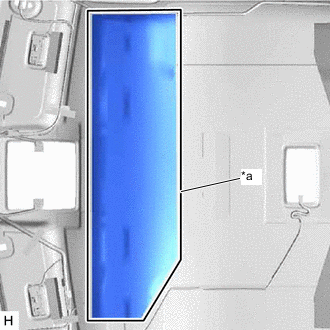
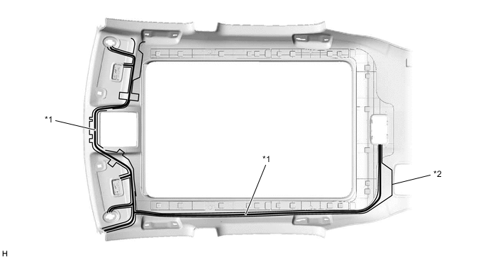
*a Silencer Marking Align the No. 1 roof silencer pad with the silencer marking on the roof headlining and install the No. 1 roof silencer pad using double-sided tape or hot-melt glue as shown in the illustration.
-
-
INSTALL NO. 2 ROOF SILENCER PAD (for Normal Roof)
-
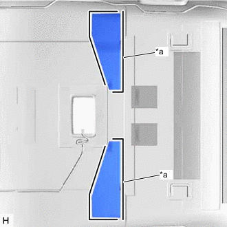
*a Silencer Marking Align the No. 2 roof silencer pads with the silencer markings on the roof headlining and install the 2 No. 2 roof silencer pads using double-sided tape or hot-melt glue as shown in the illustration.
-
-
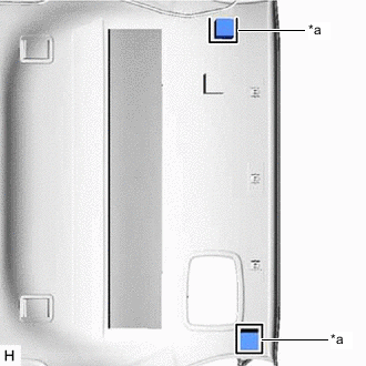
INSTALL NO. 3 ROOF SILENCER PAD (for Normal Roof)
-
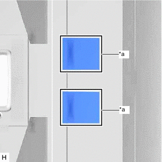
*a Silencer Marking Align the No. 3 roof silencer pads with the silencer markings on the roof headlining and install the 2 No. 3 roof silencer pads using double-sided tape or hot-melt glue as shown in the illustration.
-
-
INSTALL REAR ROOF SILENCER PAD (for Normal Roof)
-
*a Silencer Marking Align the rear roof silencer pad with the silencer marking on the roof headlining and install the rear roof silencer pad using double-sided tape or hot-melt glue as shown in the illustration.
-
-
INSTALL REAR ROOF SILENCER PAD (for Sliding Roof)
-
*a Silencer Marking Align the rear roof silencer pad with the silencer marking on the roof headlining and install the rear roof silencer pad using double-sided tape or hot-melt glue as shown in the illustration.
-
-
INSTALL NO. 4 ROOF SILENCER PAD (for Normal Roof)
-
*a Silencer Marking Align the No. 4 roof silencer pad with the silencer marking on the roof headlining and install the No. 4 roof silencer pad using double-sided tape or hot-melt glue as shown in the illustration.
-
-
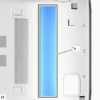
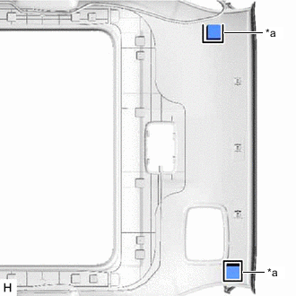
INSTALL ROOF HEADLINING PAD (for Normal Roof)
-
*a Silencer Marking Align the roof headlining pads with the silencer markings on the roof headlining and install the 2 roof headlining pads using double-sided tape or hot-melt glue as shown in the illustration.
-
-
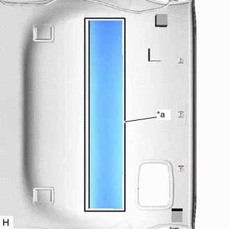
INSTALL ROOF HEADLINING PAD (for Sliding Roof)
-
*a Silencer Marking Align the roof headlining pads with the silencer markings on the roof headlining and install the 2 roof headlining pads using double-sided tape or hot-melt glue as shown in the illustration.
-
-
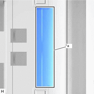
INSTALL ROOF HEADLINING PAD (for Glass Roof)
-
*a Silencer Marking Align the roof headlining pads with the silencer markings on the roof headlining and install the 2 roof headlining pads using double-sided tape or hot-melt glue as shown in the illustration.
-
-
INSTALL FRONT ROOF HEADLINING SIDE PAD (for Normal Roof)
-
*a Silencer Marking Align the front roof headlining side pads with the silencer markings on the roof headlining and install the 2 front roof headlining side pads using double-sided tape or hot-melt glue as shown in the illustration.
-
-
INSTALL ROOF HEADLINING END PAD (for Normal Roof)
-
*a Silencer Marking Align the roof headlining end pads with the silencer markings on the roof headlining and install the 2 roof headlining end pads using double-sided tape or hot-melt glue as shown in the illustration.
-
-
INSTALL ROOF HEADLINING END PAD (for Sliding Roof)
-
*a Silencer Marking Align the roof headlining end pads with the silencer markings on the roof headlining and install the 2 roof headlining end pads using double-sided tape or hot-melt glue as shown in the illustration.
-
-
INSTALL ROOF HEADLINING END PAD (for Glass Roof)
-
*a Silencer Marking Align the roof headlining end pads with the silencer markings on the roof headlining and install the 2 roof headlining end pads using double-sided tape or hot-melt glue as shown in the illustration.
-
-
INSTALL VANITY LIGHT ASSEMBLY
Tech Tips
Use the same procedure for both vanity light assemblies.
-
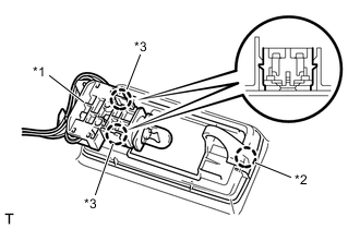
*1 Bulb Holder *2 Claw A *3 Claw B Attach claw A of the vanity light assembly to temporarily install the vanity light assembly to the roof headlining.
-
Attach the 2 claws B of the bulb holder to install the vanity light assembly.
-