UPPER INSTRUMENT PANEL REASSEMBLY
CAUTION / NOTICE / HINT
Tech Tips
-
Use the same procedure for RHD and LHD vehicles.
-
The procedure listed below is for LHD vehicles.
PROCEDURE
-
INSTALL LOWER NO. 2 INSTRUMENT PANEL FINISH PANEL
-
Install the lower No. 2 instrument panel finish panel with the 4 screws.
-
-
INSTALL INSTRUMENT PANEL FINISH PLATE
-
Install the instrument panel finish plate with the 2 screws.
-
-
INSTALL NO. 2 INSTRUMENT CLUSTER FINISH PANEL GARNISH
-
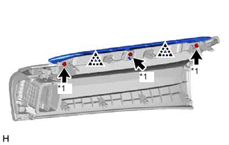
*1 Screw <A> or <B> Attach the 2 clips to install the No. 2 instrument cluster finish panel garnish.
-
Install the 3 screws <A> or <B>.
-
-
INSTALL INSTRUMENT CLUSTER FINISH PANEL ASSEMBLY (w/ Headup Display)
-
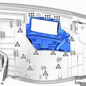
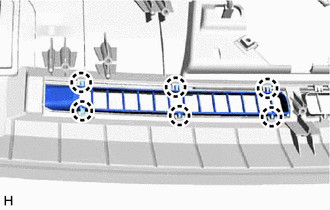
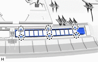
Attach the 3 guides and 10 clips to install the instrument cluster finish panel assembly.
-
-
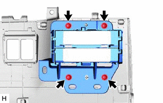
INSTALL COMBINATION METER MIRROR ECU (w/ Headup Display)
-
INSTALL INSTRUMENT PANEL WIRE
-
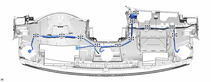
for LHD:
Attach the clamps to install the instrument panel wire.
-
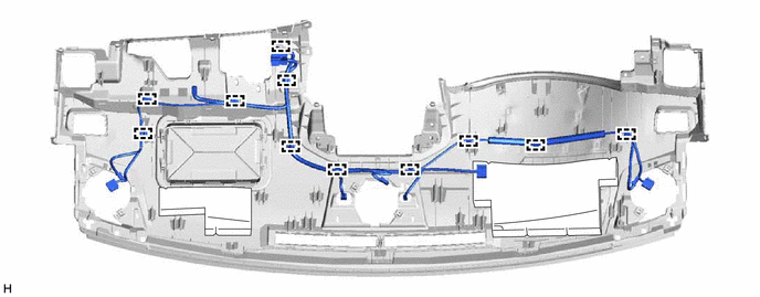
for RHD:
Attach the clamps to install the instrument panel wire.
-
-
INSTALL NAVIGATION ANTENNA ASSEMBLY
-
INSTALL INSTRUMENT PANEL PASSENGER WITHOUT DOOR AIRBAG ASSEMBLY
-
INSTALL NO. 2 INSTRUMENT PANEL WIRE
-
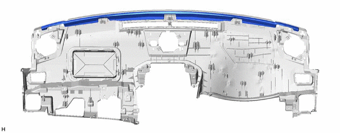
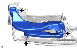
INSTALL NO. 2 INSTRUMENT PANEL CUSHION
Note
Installing the part with double-sided tape residue still remaining can cause poor adhesion. Therefore, using a cloth or other material, clean the part until the residue is completely removed (when reusing the upper instrument panel sub-assembly).
-
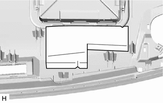
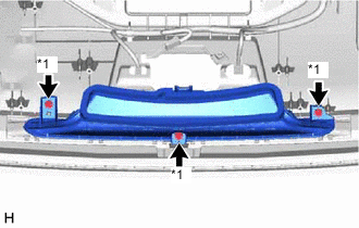
Remove the peeling paper from a new No. 2 instrument panel cushion and press firmly to install the No. 2 instrument panel cushion in the position shown in the illustration.
-
-
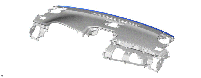
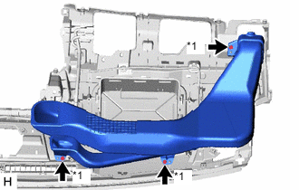
INSTALL NO. 1 INSTRUMENT PANEL CUSHION
Note
Installing the part with double-sided tape residue still remaining can cause poor adhesion. Therefore, using a cloth or other material, clean the part until the residue is completely removed (when reusing the upper instrument panel sub-assembly).
-
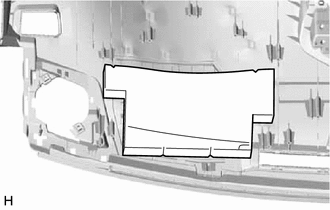
Remove the peeling paper from a new No. 1 instrument panel cushion and press firmly to install the No. 1 instrument panel cushion in the position shown in the illustration.
-
-
INSTALL NO. 4 INSTRUMENT PANEL CUSHION
-
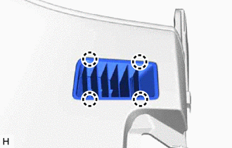
Install a new No. 4 instrument panel cushion in the location shown in the illustration using double-sided tape.
-
-
INSTALL NO. 3 INSTRUMENT PANEL CUSHION (w/o Headup Display)
-
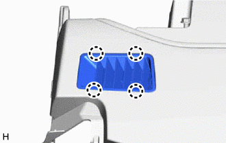
Install a new No. 3 instrument panel cushion in the location shown in the illustration using double-sided tape.
-
-
INSTALL SIDE DEFROSTER NOZZLE LH
-
Attach the 4 claws to install the side defroster nozzle LH.
-
-
INSTALL SIDE DEFROSTER NOZZLE RH
-
Attach the 4 claws to install the side defroster nozzle RH.
-
-
INSTALL NO. 2 DEFROSTER NOZZLE GARNISH
-
Attach the 6 claws to install the No. 2 defroster nozzle garnish.
-
-
INSTALL NO. 1 DEFROSTER NOZZLE GARNISH
-
Attach the 6 claws to install the No. 1 defroster nozzle garnish.
-
-
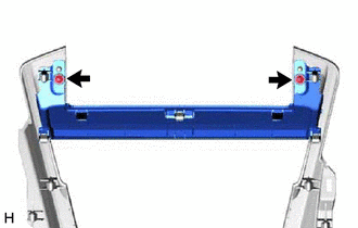
INSTALL METER HOOD SET BRACKET
-
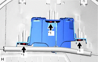
*1 Screw <A> or <B> Install the meter hood set bracket with the 3 screws <A> or <B>.
-
-
INSTALL DEFROSTER NOZZLE ASSEMBLY
-
*1 Screw <A> or <B> Install the defroster nozzle assembly with the 3 screws <A> or <B>.
-
-
INSTALL NO. 1 HEATER TO REGISTER DUCT SUB-ASSEMBLY
-
*1 Screw <A> or <B> Install the No. 1 heater to register duct sub-assembly with the 3 screws <A> or <B>.
-
-
INSTALL NO. 2 HEATER TO REGISTER DUCT SUB-ASSEMBLY
-
*1 Screw <A> or <B> Install the No. 2 heater to register duct sub-assembly with the 3 screws <A> or <B>.
-