UPPER INSTRUMENT PANEL REMOVAL
CAUTION / NOTICE / HINT
Tech Tips
-
Use the same procedure for RHD and LHD vehicles.
-
The procedure listed below is for LHD vehicles.
PROCEDURE
-
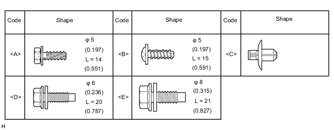
TABLE OF BOLT, SCREW AND CLIP
Tech Tips
All bolts, screws, and clips relevant to installing and removing the instrument panel are shown along with their alphabet code in the table below.
-
DISABLE AUTOAWAY/RETURN FUNCTION (for Power Tilt and Power Telescopic Steering Column)
-
Disable the autoaway/return function by changing the customize parameter.
CAUTION:
Record the current customize parameter setting (whether the autoaway/return function is enabled or disabled) in order to restore the current setting after finishing the operation.
Tech Tips
Performing the above operation causes the autoaway/return function to be disabled when the power switch is turned off.
-
Turn the power switch on (IG). Operate the tilt and telescopic switch to fully extend and lower the steering column assembly.
-
Turn the power switch off.
-
-
REMOVE NO. 3 DECK BOARD SUB-ASSEMBLY (w/ Spare Tire)
-
REMOVE REAR DECK FLOOR BOX (w/ Spare Tire)
-
REMOVE DECK FLOOR BOX LH (w/ Spare Tire)
-
PRECAUTION
Note
After turning the power switch off, waiting time may be required before disconnecting the cable from the auxiliary battery terminal. Therefore, make sure to read the disconnecting the cable from the auxiliary battery terminal notice before proceeding with work.
-
DISCONNECT CABLE FROM NEGATIVE AUXILIARY BATTERY TERMINAL
CAUTION:
Wait at least 90 seconds after disconnecting the cable from the negative (-) auxiliary battery terminal to disable the SRS system.
Note
When disconnecting the cable, some systems need to be initialized after the cable is reconnected.
-
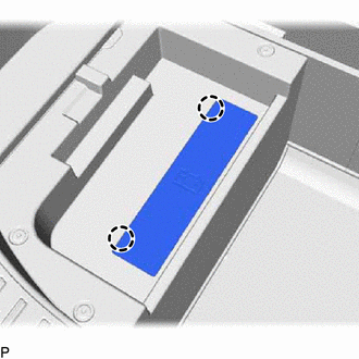
w/o Spare tire:
Detach the 2 claws and remove the battery service cover.
-
-
REMOVE DOOR SCUFF PLATE ASSEMBLY RH (for RHD)
-
REMOVE COWL SIDE TRIM BOARD RH (for RHD)
-
REMOVE CONSOLE ARMREST ASSEMBLY
-
Remove the console armrest lid.
-
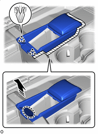

Place Hand Here 
Remove in this Direction 
Protective Tape Put protective tape around the console armrest assembly.
-
Place your hand at the position shown in the illustration and pull in the direction indicated by the arrow to detach the 2 clips.
Note
Before attempting to remove the clip on the front end of the console armrest assembly, make sure to first remove the clip on the rear end. Otherwise, the clip on the rear end may become damaged.
-
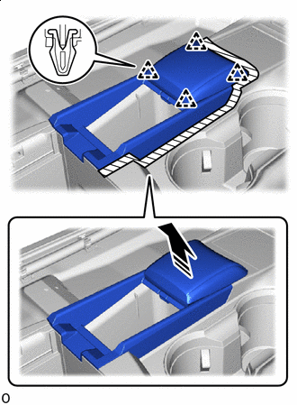
Remove in this Direction Detach the 4 clips and remove the console armrest assembly.
-
-
REMOVE UPPER REAR CONSOLE PANEL
-
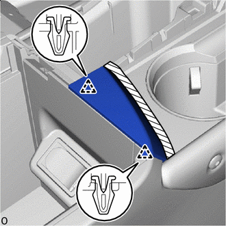
Protective Tape Put protective tape around the upper rear console panel.
-
Detach the 2 clips and remove the upper rear console panel.
-
-
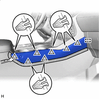
REMOVE UPPER NO. 2 CONSOLE PANEL GARNISH
-
Protective Tape Put protective tape around the upper No. 2 console panel garnish.
-
Using moulding remover B, detach the 6 clips and guide and remove the upper No. 2 console panel garnish.
-
-
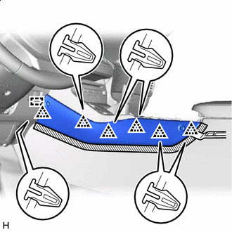
REMOVE UPPER NO. 1 CONSOLE PANEL GARNISH
-
Protective Tape Put protective tape around the upper No. 1 console panel garnish.
-
Using moulding remover B, detach the 7 clips and guide and remove the upper No. 1 console panel garnish.
-
-
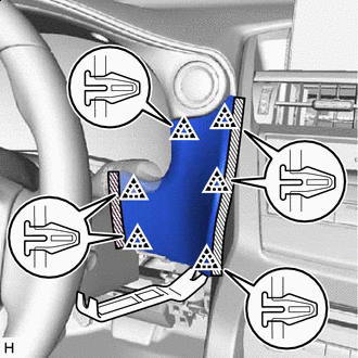
REMOVE INSTRUMENT SIDE PANEL LH
-
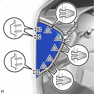
Protective Tape Put protective tape around the instrument side panel LH.
-
Using moulding remover B, detach the 5 clips and 3 guides.
-
Disconnect the connector and remove the instrument side panel LH.
-
-
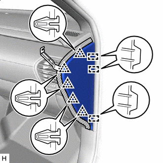
REMOVE NO. 1 INSTRUMENT PANEL SAFETY PAD SUB-ASSEMBLY
-
Protective Tape Put protective tape around the No. 1 instrument panel safety pad sub-assembly.
-
Using moulding remover B, detach the 8 clips.
-
Disconnect the connector and remove the No. 1 instrument panel safety pad sub-assembly.
-
-
REMOVE NO. 1 INSTRUMENT PANEL UNDER COVER SUB-ASSEMBLY
-
*a Screws <A> or <B> for LHD:
-
Remove the 2 screws <A> or <B>.
-
Detach the 2 claws and 2 guides.
-
Disconnect the connector, detach the clamp and remove the No. 1 instrument panel under cover sub-assembly.
-
-
*a Screws <A> or <B> for RHD:
-
Remove the 2 screws <A> or <B>.
-
Detach the 3 claws and guide.
-
Disconnect the connector, detach the clamp and remove the No. 1 instrument panel under cover sub-assembly.
-
-
-
REMOVE LOWER NO. 1 INSTRUMENT PANEL FINISH PANEL
-
*a Screws <A> or <B> Protective Tape Put protective tape around the lower No. 1 instrument panel finish panel.
-
Remove the screw <A> or <B>.
-
Using moulding remover B, detach the 13 clips and 4 claws.
-
Disconnect the connectors, detach the clamp and remove the lower No. 1 instrument panel finish panel.
-
-
REMOVE NO. 1 SWITCH HOLE BASE
-
Protective Tape Put protective tape around the No. 1 switch hole base.
-
Using moulding remover B, detach the 6 clips.
-
Disconnect the connector and remove the No. 1 switch hole base.
-
-
REMOVE INSTRUMENT SIDE PANEL RH
-
Protective Tape Put protective tape around the instrument side panel RH.
-
Using moulding remover B, detach the 5 clips and 3 guides.
-
Disconnect the connector and remove the instrument side panel RH.
-
-
REMOVE NO. 2 INSTRUMENT PANEL SAFETY PAD SUB-ASSEMBLY
-
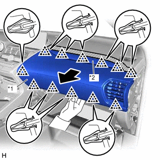
*1 No. 2 Instrument Panel Safety Pad Sub-assembly *2 No. 2 Instrument Cluster Finish Panel Garnish Protective Tape Put protective tape around the No. 2 instrument panel safety pad sub-assembly.
-
Place your hand as shown in the illustration, and then pull the No. 2 instrument panel safety pad sub-assembly in the direction indicated by the arrow shown in the illustration to detach the 12 clips and remove the No. 2 instrument panel safety pad sub-assembly together with the No. 2 instrument cluster finish panel garnish.
-
-
REMOVE INSTRUMENT PANEL FINISH PLATE
-
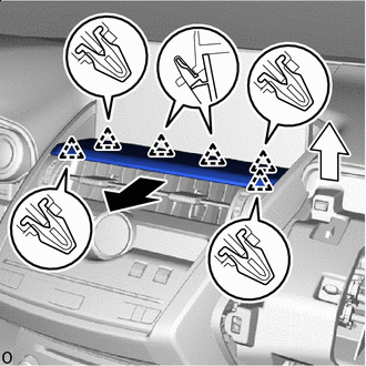

Remove in this Direction (1) 
Remove in this Direction (2) Pull in the removal direction (1) and detach the 6 clips.
-
Lift up in the removal direction (2) and remove the instrument panel finish plate.
-
-
REMOVE MULTI-DISPLAY ASSEMBLY WITH BRACKET
-
REMOVE CENTER INSTRUMENT CLUSTER FINISH PANEL ASSEMBLY
-
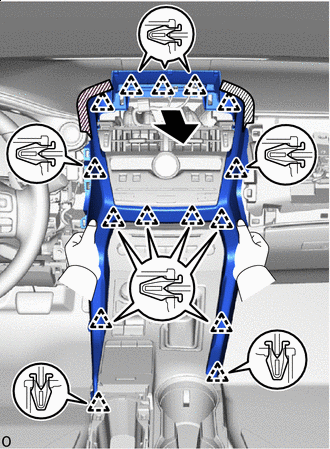
Protective Tape Put protective tape around the center instrument cluster finish panel assembly.
-
Place your hand as shown in the illustration, and then pull the center instrument cluster finish panel assembly in the direction indicated by the arrow shown in the illustration to detach the 15 clips and remove the center instrument cluster finish panel assembly.
-
-
REMOVE INSTRUMENT CLUSTER FINISH PANEL SUB-ASSEMBLY
-
*a Clip <C> Protective Tape Put protective tape around the instrument cluster finish panel sub-assembly.
-
Remove the 2 clips <C>.
-
Using a moulding remover B, detach the 5 clips and 4 claws.
-
Disconnect the connector and remove the instrument cluster finish panel sub-assembly.
-
-
REMOVE COMBINATION METER ASSEMBLY
-
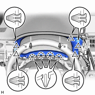
REMOVE GLOVE COMPARTMENT DOOR ASSEMBLY
-
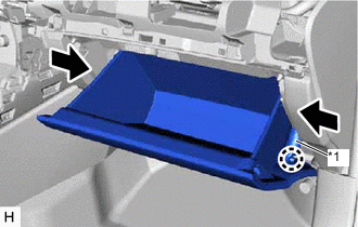
*1 Glove Compartment Door Stopper Sub-assembly Detach the claw and disconnect the glove compartment door stopper sub-assembly.
-
Slightly bend the upper part of the glove compartment door assembly to release the 2 stoppers and open the glove compartment door assembly until it is horizontal.
-
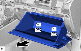
*a Hinge Pull the glove compartment door assembly toward the rear of the vehicle to detach the 2 hinges and remove it.
Note
When removing the glove compartment door assembly, make sure to pull horizontally. Pulling the glove compartment door assembly upward causes the hinges to become loose.
-
-
DISCONNECT FRONT DOOR OPENING TRIM WEATHERSTRIP LH
-
Disconnect the front door opening trim weatherstrip LH so that the front pillar garnish assembly LH can be removed.
-
-
DISCONNECT FRONT DOOR OPENING TRIM WEATHERSTRIP RH
-
Disconnect the front door opening trim weatherstrip RH so that the front pillar garnish assembly RH can be removed.
-
-
REMOVE FRONT PILLAR GARNISH ASSEMBLY LH
-
REMOVE FRONT PILLAR GARNISH ASSEMBLY RH
-
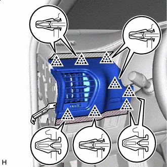
REMOVE NO. 1 INSTRUMENT PANEL SPEAKER PANEL SUB-ASSEMBLY
-
Protective Tape Put protective tape around the No. 1 instrument panel speaker panel sub-assembly.
-
Using a screwdriver, detach the 2 clips, 2 claws and 3 guides and remove the No. 1 instrument panel speaker panel sub-assembly.
Tech Tips
Tape the screwdriver tip before use.
-
-
REMOVE NO. 2 INSTRUMENT PANEL SPEAKER PANEL SUB-ASSEMBLY
-
Protective Tape Put protective tape around the No. 2 instrument panel speaker panel sub-assembly.
-
Using a screwdriver, detach the 2 clips, 2 claws and 3 guides and remove the No. 2 instrument panel speaker panel sub-assembly.
Tech Tips
Tape the screwdriver tip before use.
-
-
REMOVE NO. 1 SPEAKER OPENING COVER ASSEMBLY
-
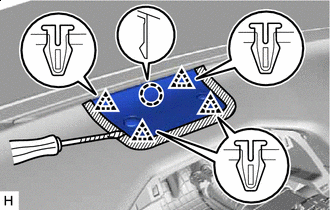
Protective Tape Put protective tape around the No. 1 speaker opening cover assembly.
-
Using a screwdriver, detach the 4 clips and claw and remove the No. 1 speaker opening cover assembly.
Tech Tips
Tape the screwdriver tip before use.
-
-
REMOVE FRONT NO. 2 SPEAKER ASSEMBLY
Tech Tips
Use the same procedure for both front No. 2 speaker assemblies.
Note
Do not touch the cone part of the front No. 2 speaker assembly.
-
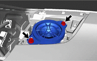
Remove the 2 screws.
-
Disconnect the connector and remove the front No. 2 speaker assembly.
-
-
REMOVE FRONT NO. 3 SPEAKER ASSEMBLY
-
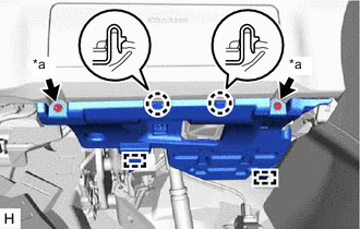
REMOVE UPPER INSTRUMENT PANEL SUB-ASSEMBLY
-
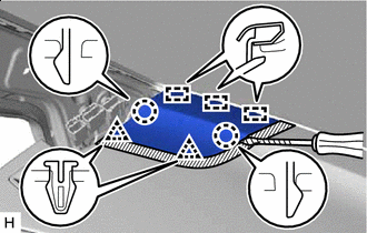
for LHD:
-
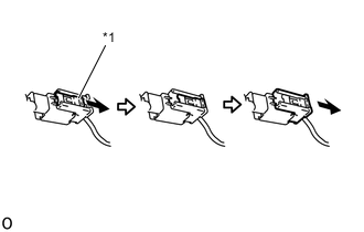
*1 Lock Slider Pull and slide the lock slider in the direction indicated by the arrow to release the connector lock and disconnect the passenger airbag connector.
Note
When handling the passenger airbag connector, take care not to damage the airbag wire harness.
-
Disconnect the connectors.
-
Remove the 2 bolts <D> and screw <A> or <B>.
-
Remove the 2 passenger airbag installation bolts <E>.
-
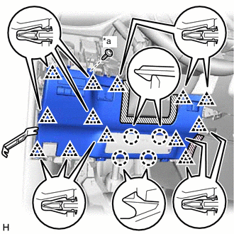
Detach the 7 clips and 5 guides and remove the upper instrument panel sub-assembly.
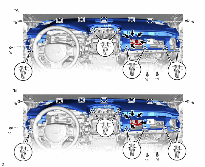
*A w/o Headup Display *B w/ Headup Display *a Passenger Airbag Connector *b Bolt <D> *c Screw <A> or <B> *d Passenger Airbag Installation Bolt <E>
-
-
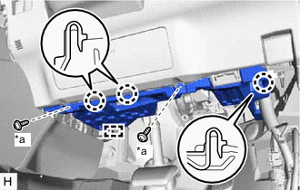
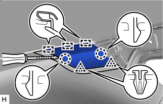
for RHD:
-
*1 Lock Slider Pull and slide the lock slider in the direction indicated by the arrow to release the connector lock and disconnect the passenger airbag connector.
Note
When handling the passenger airbag connector, take care not to damage the airbag wire harness.
-
Disconnect the connectors.
-
Remove the 2 bolts <D> and screw <A> or <B>.
-
Remove the 2 passenger airbag installation bolts <E>.
-
Detach the 7 clips and 5 guides and remove the upper instrument panel sub-assembly.
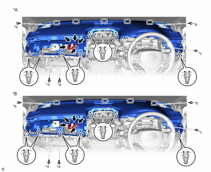
*A w/o Headup Display *B w/ Headup Display *a Passenger Airbag Connector *b Bolt <D> *c Screw <A> or <B> *d Passenger Airbag Installation Bolt <E>
-
-