LOWER INSTRUMENT PANEL INSTALLATION
CAUTION / NOTICE / HINT
Tech Tips
-
Use the same procedure for RHD and LHD vehicles.
-
The procedure listed below is for LHD vehicles.
-
A bolt without a torque specification is shown in the standard bolt chart.
PROCEDURE
-
INSTALL LOWER INSTRUMENT PANEL SUB-ASSEMBLY
-
for LHD:
-
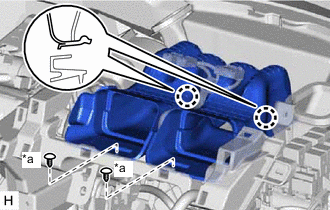
Cut off both ends at the positions shown in the illustration (runner) (when installing new part).
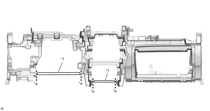
*1 Runner - - *a Cut-off Line - - -
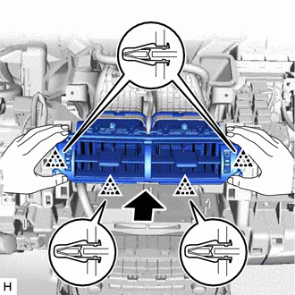
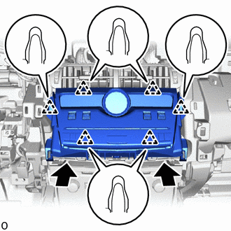
Attach the 2 guides and claw to connect the hood lock control lever sub-assembly to install the lower instrument panel sub-assembly.
-
Attach the 2 claws to connect the DLC3.
-
Connect the connector and room temperature sensor.
-
Install the screw <E>.
-
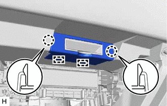
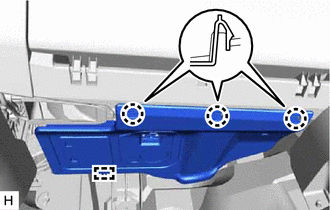
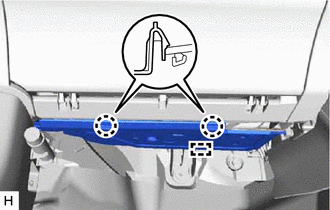
Install the 9 bolts <F> or <G>.
-
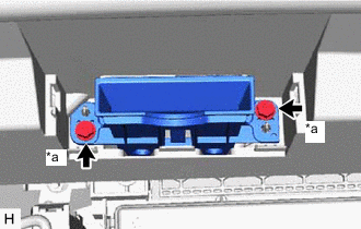
Install the 2 bolts <D>.
-
Attach the clamps.
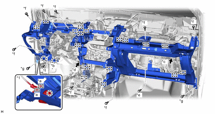
*1 Hood Lock Control Lever Sub-assembly - - *a Guide *b DLC3 *c Connector *d Room Temperature Sensor *e Screw <E> *f Bolt <F> or <G> *g Bolt <D> - -
-
-
for RHD:
-
Cut off both ends at the positions shown in the illustration (runner) (when installing new part).
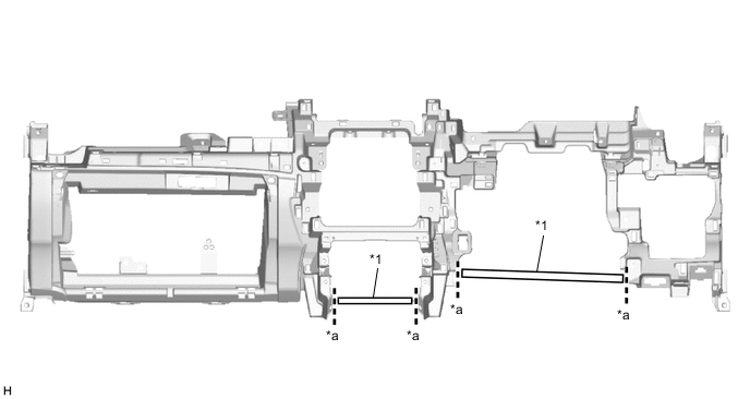
*1 Runner - - *a Cut-off Line - - -
Attach the 2 guides and claw to connect the hood lock control lever sub-assembly to install the lower instrument panel sub-assembly.
-
Attach the 2 claws to connect the DLC3.
-
Connect the connector and room temperature sensor.
-
Install the screw <E>.
-
Install the 9 bolts <F> or <G>.
-
Install the 2 bolts <D>.
-
Attach the clamps.
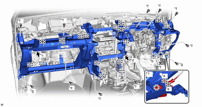
*1 Hood Lock Control Lever Sub-assembly - - *a Guide *b DLC3 *c Connector *d Room Temperature Sensor *e Screw <E> *f Bolt <F> or <G> *g Bolt <D> - -
-
-
-
INSTALL GLOVE COMPARTMENT DOOR STOPPER SUB-ASSEMBLY
-
Attach the claw to install the glove compartment door stopper sub-assembly.
-
-
INSTALL INSTRUMENT PANEL HOLE COVER (for RHD)
-
*a Screw <A> or <B> Install the instrument panel hole cover with the 2 screws <A> or <B>.
-
-
INSTALL NO. 2 INSTRUMENT PANEL HOLE COVER (for RHD)
-
Attach the 2 guides and 2 claws to install the No. 2 instrument panel hole cover.
-
-
INSTALL NO. 1 SPEAKER ASSEMBLY WITH BOX
-
INSTALL TELEMATICS TRANSCEIVER WITH BRACKET
-
INSTALL LOWER NO. 1 INSTRUMENT PANEL AIRBAG ASSEMBLY
-
INSTALL COWL SIDE TRIM BOARD LH
-
INSTALL COWL SIDE TRIM BOARD RH
-
INSTALL DOOR SCUFF PLATE ASSEMBLY LH
-
INSTALL DOOR SCUFF PLATE ASSEMBLY RH
-
INSTALL NO. 2 INSTRUMENT PANEL UNDER COVER SUB-ASSEMBLY
-
for LHD:
-
Connect the connector.
-
Attach the guide and 3 claws to install the No. 2 instrument panel under cover sub-assembly.
-
-
for RHD:
-
Connect the connector.
-
Attach the guide and 2 claws to install the No. 2 instrument panel under cover sub-assembly.
-
-
-
INSTALL RADIO RECEIVER ASSEMBLY WITH BRACKET (w/ Audio)
-
INSTALL CENTER HEATER TO REGISTER DUCT
-
*a Clip <C> Attach the 2 claws to install the center heater to register duct.
-
Install the 2 clips <C>.
-
-
INSTALL CENTER INSTRUMENT PANEL REGISTER ASSEMBLY
-
Attach the 4 clips to install the center instrument panel register assembly.
-
-
INSTALL AIR CONDITIONING CONTROL ASSEMBLY
-
Connect the connectors.
-
Attach the 6 clips to install the air conditioning control assembly.
-
-
INSTALL CONSOLE BOX ASSEMBLY
-
INSTALL UPPER INSTRUMENT PANEL SUB-ASSEMBLY
-
INSTALL HEADLIGHT DIMMER SWITCH ASSEMBLY
-
CONNECT CABLE TO NEGATIVE AUXILIARY BATTERY TERMINAL
Note
When disconnecting the cable, some systems need to be initialized after the cable is reconnected.
-
w/o Spare tire:
Attach the 2 claws to install the battery service cover.
-
-
ENABLE AUTOAWAY/RETURN FUNCTION (for Power Tilt and Power Telescopic Steering Column)
-
Restore the autoaway/return function setting to the previous condition by changing the customize parameter.
-
-
CHECK SRS WARNING LIGHT
-
INSTALL DECK FLOOR BOX LH (w/ Spare Tire)
-
INSTALL REAR DECK FLOOR BOX (w/ Spare Tire)
-
INSTALL NO. 3 DECK BOARD SUB-ASSEMBLY (w/ Spare Tire)