AIR CONDITIONING UNIT INSTALLATION
CAUTION / NOTICE / HINT
Tech Tips
-
Use the same procedure for RHD and LHD vehicles.
-
The procedure listed below is for LHD vehicles.
-
Use the same procedure for the RH and LH sides.
-
The procedure listed below is for the LH side.
-
A bolt without a torque specification is shown in the standard bolt chart.
PROCEDURE
-
INSTALL AIR CONDITIONING UNIT ASSEMBLY
-
Temporarily install the air conditioning unit assembly with the 3 bolts.
Note
To prevent damage to the installation bracket for the air conditioner unit assembly, be sure to support the air conditioner unit assembly.
-
-
INSTALL INSTRUMENT PANEL REINFORCEMENT ASSEMBLY WITH AIR CONDITIONING UNIT ASSEMBLY
-
Install the instrument panel reinforcement assembly with air conditioning unit assembly with the 7 bolts and nut.
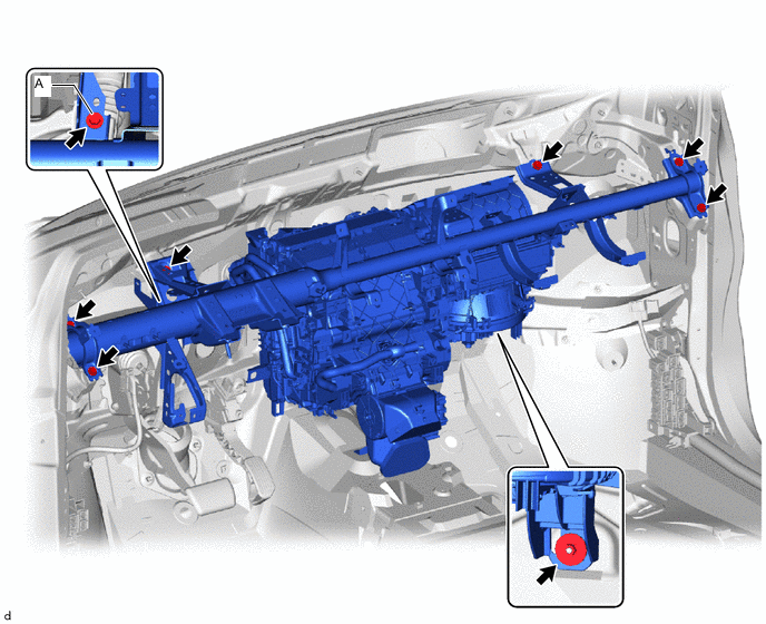
Tech Tips
Do not fully tighten the nut.
- Torque:
- Bolt A
- 18 N*m { 184 kgf*cm, 13 ft.*lbf }
-
-
INSTALL AIR DUCT ASSEMBLY
-
Install the air duct assembly with the 2 nuts.
- Torque:
- 9.8 N*m { 100 kgf*cm, 87 in.*lbf }
-
-
CONNECT INSTRUMENT PANEL WIRE
-
Connect the instrument panel wire with the bolts.
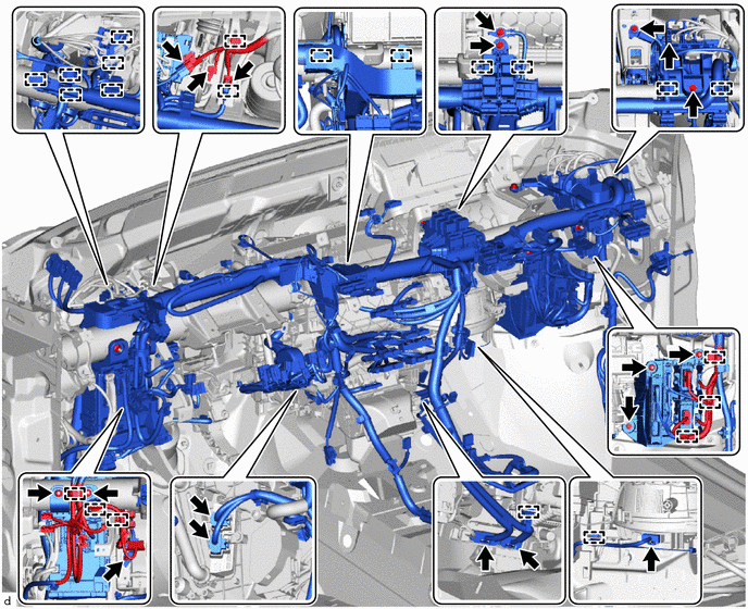
- Torque:
- 8.4 N*m { 86 kgf*cm, 74 in.*lbf }
-
Connect the ECU integration box RH with the bolt and 2 nuts.
- Torque:
- 8.4 N*m { 86 kgf*cm, 74 in.*lbf }
-
Connect the instrument panel junction block assembly with the 3 nuts.
- Torque:
- 8.4 N*m { 86 kgf*cm, 74 in.*lbf }
-
Connect the connectors and attach the clamps.
-
Connect the 3 ground wires with the 3 bolts.
- Torque:
- 8.4 N*m { 86 kgf*cm, 74 in.*lbf }
-
-
INSTALL REAR NO. 1 AIR DUCT
-
Attach the 4 claws to install the rear No. 1 air duct.
-
-
INSTALL NO. 2 INSTRUMENT PANEL BRACE SUB-ASSEMBLY
-
Install the bolt, screw, nut and No. 2 instrument panel brace sub-assembly.
Tech Tips
Do not fully tighten screw A.
-
Install the ground wire with the bolt.
- Torque:
- 8.4 N*m { 86 kgf*cm, 74 in.*lbf }
-
Attach the 3 clamps to install the wire harness.
-
-
INSTALL NO. 1 INSTRUMENT PANEL BRACE SUB-ASSEMBLY
-
Install the bolt, screw, 2 nuts and No. 1 instrument panel brace sub-assembly.
Tech Tips
Do not fully tighten screw A.
-
Attach the 4 clamps to install the wire harness.
-
-
INSTALL NO. 1 AIR DUCT
-
Attach the 3 claws to install a new No. 1 air duct.
Note
If the No. 1 air duct is reused, it may fall off or abnormal noise may occur. Therefore, make sure to replace with a new one.
-
-
INSTALL NO. 2 AIR DUCT
-
Attach the 3 claws to install a new No. 2 air duct.
Note
If the No. 2 air duct is reused, it may fall off or abnormal noise may occur. Therefore, make sure to replace with a new one.
-
Attach the clamp.
-
-
INSTALL AIR CONDITIONING UNIT ASSEMBLY
-
Tighten the 3 bolts, 2 screws and nut as shown in the illustration.
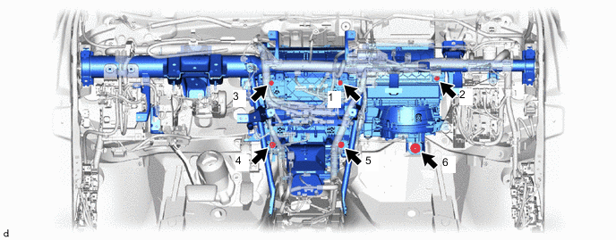
- Torque:
- 9.8 N*m { 100 kgf*cm, 87 in.*lbf }
-
-
CONNECT DRAIN COOLER HOSE
-
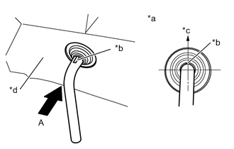
*a View A *b for LHD: Paint Mark (White)
for RHD: Paint Mark (Yellow)
*c Upward *d Engine Room Side Connect the drain cooler hose as shown in the illustration.
Note
-
Install the drain cooler hose with its paint mark facing upward.
-
Make sure that the drain cooler hose is not twisted.
-
-
-
INSTALL REAR NO. 2 AIR DUCT
-
Attach the 2 claws to install the rear No. 2 air duct.
-
Install the clip.
-
-
INSTALL REAR NO. 3 AIR DUCT
-
Attach the 2 claws to install the rear No. 3 air duct.
-
Install the clip.
-
Return the front floor carpet assembly to its original position with the 2 clips.
-
-
INSTALL FRONT SEAT ASSEMBLY LH
-
for Manual Seat:
-
for Power Seat:
-
-
INSTALL FRONT SEAT ASSEMBLY RH
Tech Tips
Use the same procedure described for the LH side.
-
INSTALL LOWER DEFROSTER NOZZLE ASSEMBLY
-
Attach the 6 claws to install the lower defroster nozzle assembly.
-
-
INSTALL STEERING COLUMN ASSEMBLY (for Manual Tilt and Manual Telescopic Steering Column)
-
INSTALL STEERING COLUMN ASSEMBLY (for Power Tilt and Power Telescopic Steering Column)
-
INSTALL LOWER INSTRUMENT PANEL
-
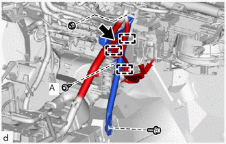
CONNECT WATER HOSE SUB-ASSEMBLY B
-
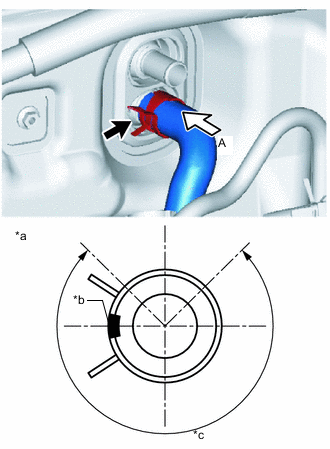
*a View A *b Water Hose Sub-assembly B Paint Mark (Yellow) *c Clip installation angle (270°) Connect the water hose sub-assembly B with the paint mark (yellow) facing left and attach the clip within the area shown in the illustration.
Note
Do not apply excessive force to the water hose sub-assembly B.
-
-
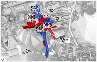
CONNECT HEATER WATER OUTLET HOSE A
-
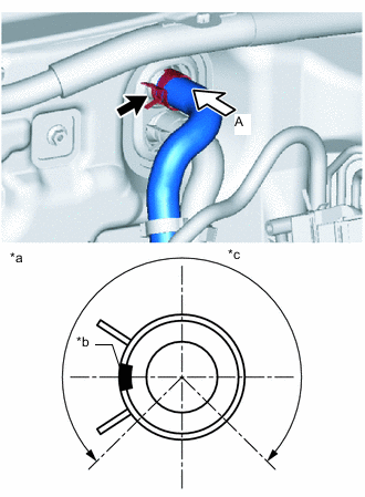
*a View A *b Heater Water Outlet Hose A Paint Mark (Yellow) *c Clip installation angle (270°) Connect the heater water outlet hose A with the paint mark (yellow) facing left and attach the clip within the area shown in the illustration.
Note
Do not apply excessive force to the heater water outlet hose A.
-
-
CONNECT LIQUID PIPE SUB-ASSEMBLY
-
Remove the vinyl tape from the liquid pipe sub-assembly.
-
Sufficiently apply compressor oil to a new O-ring and the fitting surface of the liquid pipe sub-assembly.
Compressor Oil ND-OIL 11 or equivalent -
Install the O-ring to the liquid pipe sub-assembly.
Note
Keep the O-rings and O-ring fitting surfaces free of foreign matter.
-
Connect the liquid pipe sub-assembly.
-
-
CONNECT SUCTION PIPE SUB-ASSEMBLY
-
Remove the vinyl tape from the suction pipe sub-assembly.
-
Sufficiently apply compressor oil to a new O-ring and the fitting surface of the suction pipe sub-assembly.
Compressor Oil ND-OIL 11 or equivalent -
Install the O-ring to the suction pipe sub-assembly.
Note
Keep the O-rings and O-ring fitting surfaces free of foreign matter.
-
Connect the suction pipe sub-assembly.
-
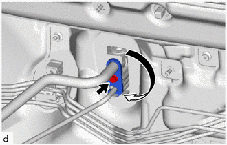
Rotate the hook connector in the direction indicated by the arrow in the illustration and install the bolt.
- Torque:
- 9.8 N*m { 100 kgf*cm, 87 in.*lbf }
-
-
ADD ENGINE COOLANT
-
CHARGE AIR CONDITIONING SYSTEM WITH REFRIGERANT
-
for HFC-134a(R134a):
-
for HFO-1234yf(R1234yf):
-
-
WARM UP COMPRESSOR
-
for HFC-134a(R134a):
-
for HFO-1234yf(R1234yf):
-
-
INSPECT FOR COOLANT LEAK
-
INSPECT FOR REFRIGERANT LEAK
-
for HFC-134a(R134a):
-
for HFO-1234yf(R1234yf):
-
-
INITIALIZATION SERVO MOTOR