AIR CONDITIONING SYSTEM SYSTEM DESCRIPTION
-
GENERAL
-
The air conditioning system has the following controls.
Control Outline Neural Network Control This control is capable of performing complex control by artificially simulating the information processing method of the nervous system of living organisms in order to establish a complex input/output relationship similar to that of a human brain. Outlet Air Temperature Control Based on the temperature set by the temperature control dial, neural network control calculates outlet air temperature based on input signals from various sensors. Dual Control The temperature settings for the driver and front passenger are controlled independently in order to provide separate vehicle interior temperatures for the right and left sides of the vehicle.
Thus, air conditioning that accommodates the occupants' preferences has been realized.
Blower Control Controls the blower motor in accordance with the airflow volume that has been calculated by neural network control based on the input signals from various sensors. Air Outlet Control Automatically switches the air outlets in accordance with the outlet mode that has been calculated by neural network control. In accordance with the engine coolant temperature, ambient air temperature, amount of sunlight, required blower, outlet temperature and vehicle speed conditions, this control automatically switches the blower outlet to foot and defroster mode to prevent the windows from becoming fogged up when the ambient air temperature is low. Air Inlet Control Automatically controls the air inlet control damper to help achieve the calculated outlet air temperature that is required. Drives the air inlet control servo motor according to the operation of the air inlet control switch and moves the dampers to the fresh or recirculation position. Electric Inverter Compressor Control Through the calculation of the target evaporator temperature based on various sensor signals, the air conditioning amplifier optimally controls discharge capacity by regulating the opening extent of the compressor solenoid valve.
The air conditioning amplifier assembly calculates the target speed of the compressor based on the target evaporator temperature (which is calculated by the cooler (room temp. sensor) thermistor, thermistor assembly, automatic light control sensor) and the actual evaporator temperature that is detected by the No. 1 cooler thermistor in order to control the compressor speed.
The air conditioning amplifier assembly calculates the target evaporator temperature, which includes corrections based on the cooler (room temp. sensor) thermistor, thermistor assembly, the automatic light control sensor, and No. 1 cooler thermistor. Accordingly, the air conditioning amplifier assembly controls the compressor speed to an extent that would not inhibit the proper cooling performance or defogging performance. Turns the A/C on automatically when the AUTO button is pressed when the blower is on and the A/C is off. Decreases the compressor speed in order to ensure quietness when the vehicle is stopped or the engine is off. Defroster Control Defroster control logic is used to improve defroster performance. PTC Heater Control*1 When the hybrid control system is operating (READY), and the blower motor with fan sub-assembly is turned on, the air conditioning amplifier assembly turns on the quick heater assembly if the conditions listed below are met.
-
Engine coolant temperature is below specified temperature.
-
Outside temperature is below specified temperature.
-
Tentative air mix damper opening angle is above the specified value (MAX HOT).
Blower Customize*2 During automatic air conditioning operation, the air volume can be adjusted in 3 levels using the FAST SOFT switch: MEDIUM → SOFT (small air volume) → FAST (large air volume). ECO Mode Control When the integration control and panel assembly (ECO mode switch) is turned on, the air conditioning amplifier assembly limits the air conditioning system performance. Diagnosis A Diagnostic Trouble Code (DTC) is stored in memory when the air conditioning amplifier detects a problem with the air conditioning system. *1: w/ PTC Heater
*2: w/ Follow Me Home System
-
-
-
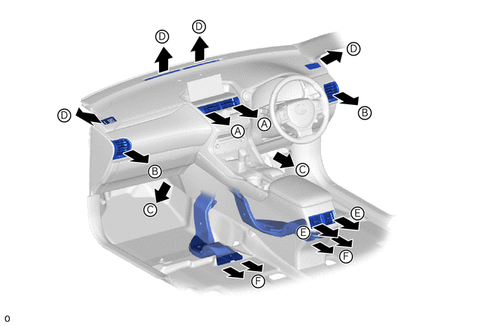
MODE POSITION AND DAMPER OPERATION
-
Mode Position and Damper Operation
-
Front
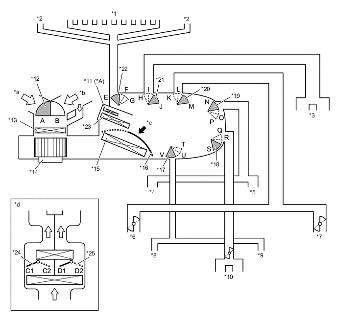
*A w/ PTC Heater - - *1 Front Defroster *2 Side Defroster *3 Center Defroster *4 To Front Passenger Side Footwell Register Duct *5 To Driver Side Footwell Register Duct *6 To Front Passenger Side Side Register Duct *7 To Driver Side Side Register Duct *8 To Front Passenger Side Rear Heater Duct *9 To Driver Side Rear Heater Duct *10 To Console Box Register *11 Quick Heater Assembly *12 Recirculated Air Door *13 Air Refiner Element *14 Blower Motor with Fan Sub-assembly *15 No. 1 Cooler Evaporator Sub-assembly *16 Air Mix Control Door *17 Mode Control Door (for Rear Heater Duct) *18 Mode Control Door (for Rear Console Register) *19 Mode Control Door (for Front Footwell Register Duct) *20 Mode Control Door (for Front and Side Register) *21 Mode Control Door (for Center Register) *22 Mode Control Door (for Defroster) *23 Heater Radiator Unit Sub-assembly *24 Air Mix Control Door (for Driver Side) *25 Air Mix Control Door (for Front Passenger Side) - - *a Fresh Air *b Recirculated Air *c View from A *d View from A Image Functions of Main Dampers Control Damper Operation Position Damper Position Operation Air Inlet Control Damper FRESH B Allows fresh air to enter. RECIRCULATION A Causes internal air to recirculate. Air Mix Control Damper Temperature Setting: 30°C (86°F) to 16°C (61°F) C1 - C2
(for Driver Side)
Varies the front passenger side mixture ratio of the fresh air and the recirculation air in order to regulate the temperature continuously from HI to LO. D1 - D2
(for Front Passenger Side)
Varies the driver side mixture ratio of the fresh air and the recirculation air in order to regulate the temperature continuously from HI to LO. Air Outlet Control Damper DEF

G, H, L, N, Q, V Defrosts the windshield through the front defroster, side defrosters and side registers. FOOT / DEF

G, H, L, P, Q, T Defrosts the windshield through the footwell register dect, rear heater duct, front and side defroster, side register and console box register. FOOT

F, H, L, P, Q, T Air blows out of side register, foot well register duct, rear heater duct and front and side defroster, side register and console box register. BI-LEVEL

E, I, L, O, R, U Air blows out of center and side registers, footwell register duct, console box register and rear heater duct. FACE

E, J, M, N, S, V Air blows out of center and side registers and console box registers.
-
-
-
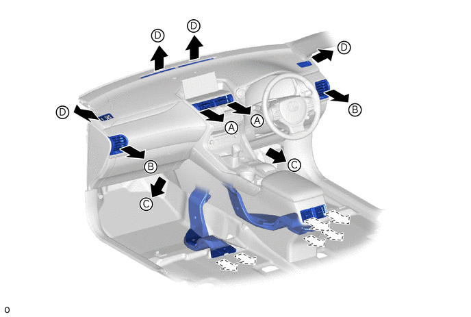
AIR OUTLETS AND AIRFLOW VOLUME
-
Air Outlets and Airflow Volume (for All Seat Control Modes)
Mode A B C D E F Center Register Side Register Footwell Resigter Defroster Console Box Register Rear Heater Duct 
FACE 
- - - 
BI-LEVEL 
- 
FOOT - 

FOOT/DEF - 
DEF - - - - The size of each circle ○ indicates the ratio of air flow volume.
-
Air Outlets and Air flow Volume (for Front Seat Control Modes)
Mode A B C D E F Center Register Side Register Footwell Resigter Defroster Console Box Register Rear Heater Duct FACE - - - - BI-LEVEL - - - FOOT - - - FOOT/DEF - - - The size of each circle ○ indicates the ratio of air flow volume.
-