REAR SEAT ASSEMBLY(for Power Seat) INSPECTION
PROCEDURE
-
PRECAUTION
Note
After performing the following check, initialize the fold seat control ECU (initial position reset and initial position memorization).
-
INSPECT REAR SEATBACK FRAME SUB-ASSEMBLY LH
-
Check the operation of the reclining motor.
-
Apply auxiliary battery voltage to the reclining motor connector, and check that the rear seatback frame sub-assembly LH operates smoothly as follows.
Note
-
Connect the auxiliary battery simultaneously to motor A and motor B to perform an inspection.
-
Do not apply voltage to terminals 2, 5 and 6 of the connector for motor A.
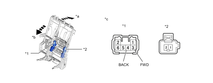
*1 Motor A *2 Motor B *a Forward *b Backward *c Component without wire harness connected
(Rear Seatback Frame sub-assembly LH)
- - OK Condition Specified Condition Auxiliary battery positive (+) → Terminal 3 (FWD (Motor A))
Auxiliary battery negative (-) → Terminal 4 (BACK (Motor A))
Forward Auxiliary battery positive (+) → Terminal 1 (Motor B)
Auxiliary battery negative (-) → Terminal 2 (Motor B)
Auxiliary battery positive (+) → Terminal 4 (BACK (Motor A))
Auxiliary battery negative (-) → Terminal 3 (FWD (Motor A))
Backward Auxiliary battery positive (+) → Terminal 2 (Motor B)
Auxiliary battery negative (-) → Terminal 1 (Motor B)
If the result is not as specified, replace the rear seatback frame sub-assembly LH.
-
-
-
-
INSPECT REAR SEATBACK FRAME SUB-ASSEMBLY RH
-
Check the operation of the reclining motor.
-
Apply auxiliary battery voltage to the reclining motor connector, and check that the rear seatback frame sub-assembly RH operates smoothly as follows.
Note
-
Connect the auxiliary battery simultaneously to motor A and motor B to perform an inspection.
-
Do not apply voltage to terminals 2, 5 and 6 of the connector for motor A.
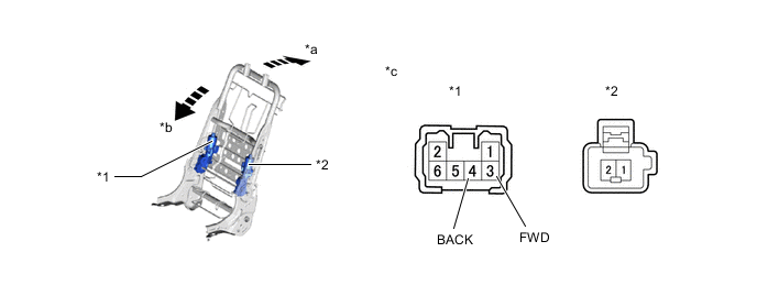
*1 Motor A *2 Motor B *a Forward *b Backward *c Component without wire harness connected
(Rear Seatback Frame sub-assembly RH)
- - OK Condition Specified Condition Auxiliary battery positive (+) → Terminal 3 (FWD (Motor A))
Auxiliary battery negative (-) → Terminal 4 (BACK (Motor A))
Forward Auxiliary battery positive (+) → Terminal 1 (Motor B)
Auxiliary battery negative (-) → Terminal 2 (Motor B)
Auxiliary battery positive (+) → Terminal 4 (BACK (Motor A))
Auxiliary battery negative (-) → Terminal 3 (FWD (Motor A))
Backward Auxiliary battery positive (+) → Terminal 2 (Motor B)
Auxiliary battery negative (-) → Terminal 1 (Motor B)
If the result is not as specified, replace the rear seatback frame sub-assembly RH.
-
-
-