REAR POWER SEAT CONTROL SYSTEM Fold Seat Switch Circuit
DESCRIPTION
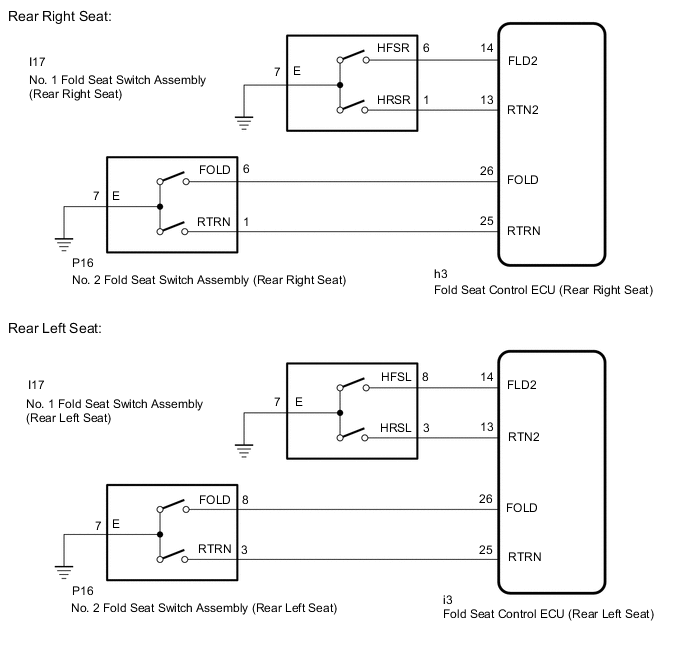
When the fold seat switch is operated, a switch operation signal is sent to the fold seat control ECU. The ECU receives switch operation signals from each switch and activates the reclining motor and cushion motor.
WIRING DIAGRAM
PROCEDURE
-
CHECK FOLD SEAT CONTROL ECU (FOLD SEAT SWITCH SIGNAL)
-
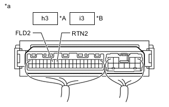
*A Rear Right Seat *B Rear Left Seat *a Component with harness connected (Fold Seat Control ECU) Check the No. 1 fold seat switch signal.
-
Remove the fold seat control ECU with its connectors still connected.
-
Measure the voltage according to the value(s) in the table below.
Standard Voltage Rear Right Seat Tester Connection Condition Specified Condition h3-14 (FLD2) - Body ground Fold switch of No. 1 fold seat switch (for Rear Right Switch) off → on 11 to 14 V → Below 1 V h3-13 (RTN2) - Body ground Return switch of No. 1 fold seat switch (for Rear Right Switch) off → on 11 to 14 V → Below 1 V Rear Left Seat Tester Connection Condition Specified Condition i3-14 (FLD2) - Body ground Fold switch of No. 1 fold seat switch (for Rear Left Switch) off → on 11 to 14 V → Below 1 V i3-13 (RTN2) - Body ground Return switch of No. 1 fold seat switch (for Rear Left Switch) off → on 11 to 14 V → Below 1 V
-
-
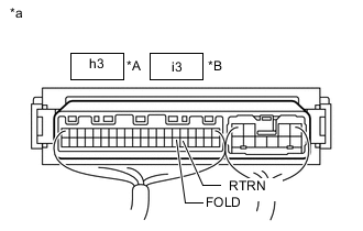
*A Rear Right Seat *B Rear Left Seat *a Component with harness connected (Fold Seat Control ECU) Check No. 2 fold seat switch signal.
-
Remove the fold seat control ECU with its connectors still connected.
-
Measure the voltage according to the value(s) in the table below.
Standard Voltage Rear Right Seat Tester Connection Condition Specified Condition h3-26 (FOLD) - Body ground Fold switch of No. 2 fold seat switch (for Rear Right Switch) off → on 11 to 14 V → Below 1 V h3-25 (RTRN) - Body ground Return switch of No. 2 fold seat switch (for Rear Right Switch) off → on 11 to 14 V → Below 1 V Rear Left Seat Tester Connection Condition Specified Condition i3-26 (FOLD) - Body ground Fold switch of No. 2 fold seat switch (for Rear Left Switch) off → on 11 to 14 V → Below 1 V i3-25 (RTRN) - Body ground Return switch of No. 2 fold seat switch (for Rear Left Switch) off → on 11 to 14 V → Below 1 V Result Result Proceed to OK A NG (No. 1 fold seat switch) B NG (No. 2 fold seat switch) C
-
A 
PROCEED TO NEXT SUSPECTED AREA SHOWN IN PROBLEM SYMPTOMS TABLE Click here
C 
INSPECT NO. 2 FOLD SEAT SWITCH ASSEMBLY Click here
B 
-
-
INSPECT NO. 1 FOLD SEAT SWITCH ASSEMBLY
-
Remove the No. 1 fold seat switch assembly.
-
Inspect the No. 1 fold seat switch assembly.
Result Result OK NG
NG
REPLACE NO. 1 FOLD SEAT SWITCH ASSEMBLY Click here
OK
-
-
CHECK HARNESS AND CONNECTOR (NO. 1 FOLD SEAT SWITCH ASSEMBLY - FOLD SEAT CONTROL ECU AND BODY GROUND)
-
Disconnect the I17 No. 1 fold seat switch assembly connector.
-
Disconnect the h3*1 or i3*2 ECU connector.
-
*1: Rear Right Seat
-
*2: Rear Left Seat
-
-
Measure the resistance according to the value(s) in the table below.
Standard Resistance Rear Right Seat Tester Connection Condition Specified Condition I17-6 (HFSR) - h3-14 (FLD2) Always Below 1 Ω I17-6 (HFSR) or h3-14 (FLD2) - Body ground Always 10 kΩ or higher I17-1 (HRSR) - h3-13 (RTN2) Always Below 1 Ω I17-1 (HRSR) or h3-13 (RTN2) - Body ground Always 10 kΩ or higher I17-7 (E) - Body ground Always Below 1 Ω Rear Left Seat Tester Connection Condition Specified Condition I17-8 (HFSL) - i3-14 (FLD2) Always Below 1 Ω I17-8 (HFSL) or i3-14 (FLD2) - Body ground Always 10 kΩ or higher I17-3 (HRSL) - i3-13 (RTN2) Always Below 1 Ω I17-3 (HRSL) or i3-13 (RTN2) - Body ground Always 10 kΩ or higher I17-7 (E) - Body ground Always Below 1 Ω Result Result OK NG
OK
REPLACE FOLD SEAT CONTROL ECU Click here
NG
REPAIR OR REPLACE HARNESS OR CONNECTOR
-
-
INSPECT NO. 2 FOLD SEAT SWITCH ASSEMBLY
-
Remove the No. 2 fold seat switch assembly.
-
Inspect the No. 2 fold seat switch assembly.
Result Result OK NG
NG
REPLACE NO. 2 FOLD SEAT SWITCH ASSEMBLY Click here
OK
-
-
CHECK HARNESS AND CONNECTOR (NO. 2 FOLD SEAT SWITCH ASSEMBLY - FOLD SEAT CONTROL ECU AND BODY GROUND)
-
Disconnect the P16 No. 2 fold seat switch assembly connector.
-
Disconnect the h3*1 or i3*2 fold seat control ECU connector.
-
*1: Rear Right Seat
-
*2: Rear Left Seat
-
-
Measure the resistance according to the value(s) in the table below.
Standard Resistance Rear Right Seat Tester Connection Condition Specified Condition P16-6 (FOLD) - h3-26 (FOLD) Always Below 1 Ω P16-6 (FOLD) or h3-26 (FOLD) - Body ground Always 10 kΩ or higher P16-1 (RTRN) - h3-25 (RTRN) Always Below 1 Ω P16-1 (RTRN) or h3-25 (RTRN) - Body ground Always 10 kΩ or higher P16-7 (E) - Body ground Always Below 1 Ω Rear Left Seat Tester Connection Condition Specified Condition P16-8 (FOLD) - i3-26 (FOLD) Always Below 1 Ω P16-8 (FOLD) or i3-26 (FOLD) - Body ground Always 10 kΩ or higher P16-3 (RTRN) - i3-25 (RTRN) Always Below 1 Ω P16-3 (RTRN) or i3-25 (RTRN) - Body ground Always 10 kΩ or higher P16-7 (E) - Body ground Always Below 1 Ω Result Result OK NG
OK
REPLACE FOLD SEAT CONTROL ECU Click here
NG
REPAIR OR REPLACE HARNESS OR CONNECTOR
-