SEAT HEATER SYSTEM TERMINALS OF ECU
-
CHECK AIR CONDITIONING AMPLIFIER ASSEMBLY
-
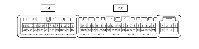
Disconnect the I50 air conditioning amplifier assembly connector.
-
Measure the voltage and resistance according to the value(s) in the table below.
Tester Connection Wiring Color Terminal Description Condition Specified Condition I50-1 (IG+) - Body ground SB - Body ground IG power supply Power switch on (IG) 11 to 14 V Power switch off Below 1 V I50-14 (GND) - Body ground W-B - Body ground Ground Always Below 1 Ω I50-21 (B) - Body ground GR - Body ground Battery power supply Power switch off 11 to 14 V -
Reconnect the I50 air conditioning amplifier assembly connector.
-
Measure the voltage and resistance according to the value(s) in the table below.
-
Check for pulse generation according to the value(s) in the table below.
Tester Connection Wiring Color Terminal Description Condition Specified Condition I50-16 (SHP+) - Body ground V - Body ground Seat heater (for Front Passenger Side) drive signal
-
Power switch on (IG)
-
Seat heater switch (for Front Passenger Side) on
Below 1 V I50-17 (SHD+) - Body ground LG - Body ground Seat heater (for Driver Side) input signal
-
Power switch on (IG)
-
Seat heater switch (for Driver Side) on
Below 1 V I50-18 (SHPE) - Body ground* GR - Body ground Seat heater (for Rear RH) input signal
-
Power switch on (IG)
-
Refreshing seat switch (for Rear RH) on
Below 1 V I50-36 (SHDE) - Body ground* LG - Body ground Seat heater (for Rear LH) input signal
-
Power switch on (IG)
-
Refreshing seat switch (for Rear LH) on
Below 1 V I50-37 (LIN1) - Body ground B - Body ground Seat heater switch signal Power switch on (IG) Pulse generation I54-3 (TSR) - I54-7 (SG-3) P - R Seat heater sensor (for Front Passenger Side) input signal Power switch off
(0 to 30°C [32 to 86°F])
-
0°C(32°F): 23.74 kΩ
-
30°C(86°F): 8.441 kΩ
I54-4 (TSL) - I54-8 (SG-6) W - G Seat heater sensor (for Driver Side) input signal Power switch off
(0 to 30°C [32 to 86°F])
-
0°C(32°F): 23.74 kΩ
-
30°C(86°F): 8.441 kΩ
I54-5 (TFAR) - I54-23 (SG-7)* R - W Seat heater sensor (for Rear RH) input signal Power switch off
(0 to 30°C [32 to 86°F])
-
0°C(32°F): 23.74 kΩ
-
30°C(86°F): 8.441 kΩ
I54-7 (SG-3) - Body ground R - Body ground Ground for seat heater sensor (for Front Passenger Side) Always Below 1 Ω I54-8 (SG-6) - Body ground G - Body ground Ground for seat heater sensor (for Driver Side) Always Below 1 Ω I54-20 (TFAL) - I54-23 (SG-7)* G - W Seat heater sensor (for Rear LH) input signal Power switch off
(0 to 30°C [32 to 86°F])
-
0°C(32°F): 23.74 kΩ
-
30°C(86°F): 8.441 kΩ
I54-16 (RLIN) - Body ground* V - Body ground Refreshing seat switch signal (LIN) Power switch on (IG) Pulse generation (See waveform) I54-23 (SG-7) - Body ground* W - Body ground Ground for seat heater sensor (for Rear LH and RH) Always Below 1 Ω
-
*: w/ Rear Seat Heater
-
-
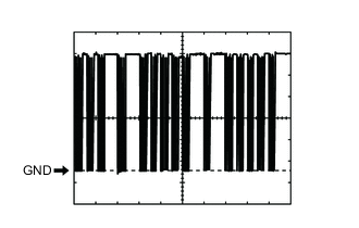
Wavefrom:
Item Content Terminal No. I54-16 (RLIN) - Body ground* Tool Setting 2 V/DIV., 20 μs/DIV. Vehicle Condition Power switch on (IG)
-
*: w/ Rear Seat Heater
-
-
-
CHECK AIR CONDITIONING CONTROL ASSEMBLY
-
REFRESHING SEAT SWITCH (w/ Rear Seat Heater)
-
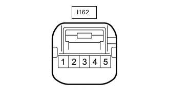
Disconnect the I162 refreshing seat switch connector.
-
Measure the voltage and resistance according to the value(s) in the table below.
Tester Connection Wiring Color Terminal Description Condition Specified Condition I162-1 (E) - Body ground BR - Body ground Ground Always Below 1 Ω I162-5 (IG+) - Body ground R - Body ground IG power supply Power switch on (IG) 11 to 14 V Power switch off Below 1 V -
Reconnect the I162 refreshing seat switch connector.
-
Check for pulse generation according to the value(s) in the table below.
Tester Connection Wiring Color Terminal Description Condition Specified Condition I162-3 (RLIN) - Body ground V - Body ground Refreshing seat switch signal (LIN) Power switch on (IG) Pulse generation (See waveform) -
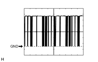
Wavefrom:
Item Content Terminal No. I162-3 (RLIN) - Body ground Tool Setting 2 V/DIV., 20 μs/DIV. Vehicle Condition Power switch on (IG)
-