FRONT AIRBAG SENSOR INSTALLATION
CAUTION / NOTICE / HINT
Tech Tips
-
Use the same procedure for the RH and LH sides.
-
The procedure listed below is for the LH side.
PROCEDURE
-
INSTALL FRONT AIRBAG SENSOR LH
-
Check that the power switch is off.
-
Check that the cable is disconnected from the auxiliary battery negative (-) terminal.
CAUTION:
Wait at least 90 seconds after disconnecting the cable from the auxiliary battery negative (-) terminal to disable the SRS system.
-
Attach the guide and hold the front airbag sensor LH in place.
-
Install the bolt.
- Torque:
- 9.0 N*m { 92 kgf*cm, 80 in.*lbf }
Note
-
If the front airbag sensor LH has been dropped, replace it with a new one.
-
When installing the front airbag sensor LH, be careful that the SRS wiring does not interfere with or is not pinched between other parts.
-
Tighten the bolt while holding the front airbag sensor LH because the front airbag sensor LH guide is easily damaged.
-
Connect the airbag connector.
Note
When connecting any airbag connector, take care not to damage the airbag wire harness.
-
Before connecting the connector, check that the position of the housing lock is correct as shown in the illustration.
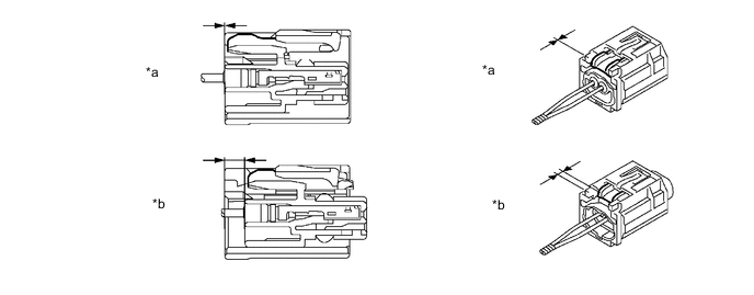
*a Incorrect *b Correct -
While holding the CPA be sure to engage the connectors until they are locked and check that the CPA is in its original position (when locking, make sure that a click sound can be heard).
Tech Tips
When engaged, the white housing lock will slide. Be sure not to hold the white housing lock and upper part of the CPA, as it may result in an insecure fit.
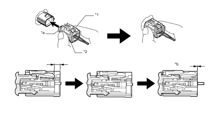
*1 Housing Lock *2 CPA *a CPA Upper Part *b Connection is Completed
-
-
Check that there is no looseness in the installation parts of the front airbag sensor LH.
-
-
INSTALL FRONT BUMPER ASSEMBLY
except Sport Package:
for Sport Package:
-
CONNECT CABLE TO NEGATIVE AUXILIARY BATTERY TERMINAL
Note
When disconnecting the cable, some systems need to be initialized after the cable is reconnected.
-
Connect the auxiliary battery negative (-) terminal and tighten the nut.
- Torque:
- 5.4 N*m { 55 kgf*cm, 48 in.*lbf }
-
w/o Spare Tire:
Attach the 2 claws to install the battery service cover.
-
-
INSTALL DECK FLOOR BOX LH (w/ Spare Tire)
-
INSTALL REAR DECK FLOOR BOX (w/ Spare Tire)
-
INSTALL NO. 3 DECK BOARD SUB-ASSEMBLY (w/ Spare Tire)
-
PERFORM DIAGNOSTIC SYSTEM CHECK
-
CHECK SRS WARNING LIGHT