SPIRAL CABLE REMOVAL
PROCEDURE
-
REMOVE NO. 3 DECK BOARD SUB-ASSEMBLY (w/ Spare Tire)
-
REMOVE REAR DECK FLOOR BOX (w/ Spare Tire)
-
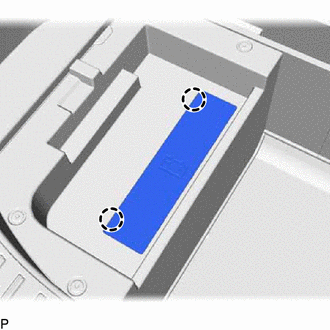
REMOVE DECK FLOOR BOX LH (w/ Spare Tire)
-
PRECAUTION
Note
After turning the power switch off, waiting time may be required before disconnecting the cable from the auxiliary battery negative (-) terminal. Therefore, make sure to read the disconnecting the cable from the auxiliary battery negative (-) terminal notice before proceeding with work.
-
DISCONNECT CABLE FROM NEGATIVE AUXILIARY BATTERY TERMINAL
CAUTION:
Wait at least 90 seconds after disconnecting the cable from the auxiliary battery negative (-) terminal to disable the SRS system.
Note
When disconnecting the cable, some systems need to be initialized after the cable is reconnected.
-
w/o Spare Tire:
Detach the 2 claws and remove the battery service cover.
-
Loosen the nut and disconnect the auxiliary battery negative (-) terminal.
-
-
PLACE FRONT WHEELS FACING STRAIGHT AHEAD
-
REMOVE STEERING WHEEL ASSEMBLY
-
INSPECT SPIRAL WITH SENSOR CABLE SUB-ASSEMBLY
-
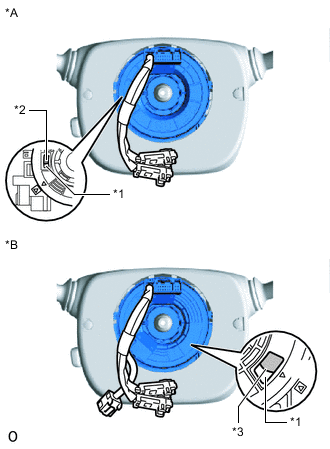
*A w/o Steering Heater *B w/ Steering Heater *1 Check Window *2 Colored Roller *3 U-turn Point Check the check window shown in the illustration.
Note
When the following conditions cannot be checked via the check window with the front wheels facing straight ahead, there may be a malfunction in the spiral with sensor cable sub-assembly. In this case, replace the spiral cable sensor sub-assembly with a new one.
-
w/o Steering Heater:
With the steering wheel straight ahead, the colored roller can be checked from the check window.
-
w/ Steering Heater:
With the steering wheel straight ahead, the U-turn point of the cable can be checked from the check window.
-
-
-
REMOVE LOWER STEERING COLUMN COVER
for Manual Tilt and Manual Telescopic Steering Column:
for Power Tilt and Power Telescopic Steering Column:
-
REMOVE UPPER STEERING COLUMN COVER
for Manual Tilt and Manual Telescopic Steering Column:
for Power Tilt and Power Telescopic Steering Column:
-
REMOVE SPIRAL WITH SENSOR CABLE SUB-ASSEMBLY
Note
-
Do not replace the spiral with sensor cable sub-assembly with the auxiliary battery connected and the power switch on (IG).
-
Do not rotate the spiral with sensor cable sub-assembly with the battery connected and the power switch on (IG).
-
When rotating the spiral with sensor cable sub-assembly to check the operation of the sub-assembly (checking for abnormal noise, checking the Data List, etc.), make sure to perform the inspection with the steering wheel assembly installed.
-
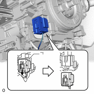
*1 Slider Slide the slider to release the lock, and then disconnect the airbag connector.
Note
When disconnecting any airbag connector, take care not to damage the airbag wire harness.
-
Disconnect each connector.
-
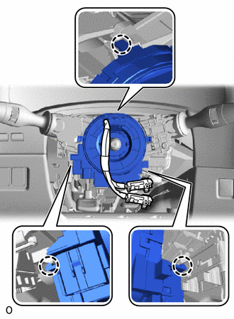
Detach the 3 claws and remove the spiral with sensor cable sub-assembly.
-