SPIRAL CABLE REMOVAL
PROCEDURE
-
REMOVE NO. 3 DECK BOARD SUB-ASSEMBLY (w/ Spare Tire)
-
REMOVE REAR DECK FLOOR BOX (w/ Spare Tire)
-
REMOVE DECK FLOOR BOX LH (w/ Spare Tire)
-
PRECAUTION
Note
After turning the power switch off, waiting time may be required before disconnecting the cable from the auxiliary battery negative (-) terminal. Therefore, make sure to read the disconnecting the cable from the auxiliary battery negative (-) terminal notice before proceeding with work.
-
DISCONNECT CABLE FROM NEGATIVE AUXILIARY BATTERY TERMINAL
CAUTION:
Wait at least 90 seconds after disconnecting the cable from the auxiliary battery negative (-) terminal to disable the SRS system.
Note
When disconnecting the cable, some systems need to be initialized after the cable is reconnected.
-
w/o Spare Tire:
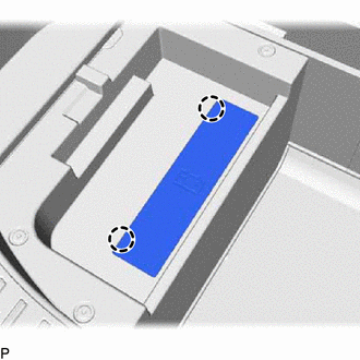
Detach the 2 claws and remove the battery service cover.
-
Loosen the nut and disconnect the auxiliary battery negative (-) terminal.
-
-
PLACE FRONT WHEELS FACING STRAIGHT AHEAD
-
REMOVE STEERING WHEEL ASSEMBLY
-
INSPECT SPIRAL WITH SENSOR CABLE SUB-ASSEMBLY
-
Check that the front wheels are facing straight ahead.
-
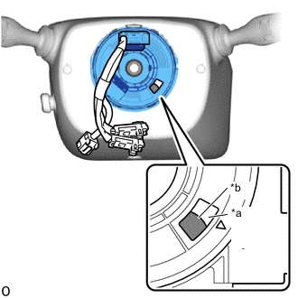
*a Check Window *b Top of Flat Cable U-turn Check that the spiral cable sub-assembly with sensor is center position.
OK The connector is at the top. The top of the flat cable U-turn can be checked from the check window. Note
If the result is not as specified, it is possible that the spiral cable sub-assembly with sensor is broken. Replace the spiral cable sub-assembly with sensor with a new one.
-
-
REMOVE LOWER STEERING COLUMN COVER
for Manual Tilt and Manual Telescopic Steering Column:
for Power Tilt and Power Telescopic Steering Column:
-
REMOVE UPPER STEERING COLUMN COVER
for Manual Tilt and Manual Telescopic Steering Column:
for Power Tilt and Power Telescopic Steering Column:
-
REMOVE SPIRAL WITH SENSOR CABLE SUB-ASSEMBLY
Note
-
Do not replace the spiral with sensor cable sub-assembly with the auxiliary battery connected and the power switch on (IG).
-
Do not rotate the spiral with sensor cable sub-assembly with the battery connected and the power switch on (IG).
-
When rotating the spiral with sensor cable sub-assembly to check the operation of the sub-assembly (checking for abnormal noise, checking the Data List, etc.), make sure to perform the inspection with the steering wheel assembly installed.
-
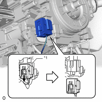
*1 Slider Slide the slider to release the lock, and then disconnect the airbag connector.
Note
When disconnecting any airbag connector, take care not to damage the airbag wire harness.
-
Disconnect each connector.
-
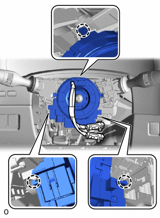
Detach the 3 claws and remove the spiral with sensor cable sub-assembly.
-