METER / GAUGE SYSTEM Headup Display Malfunction
DESCRIPTION
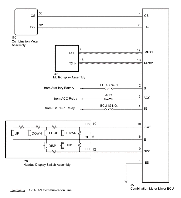
This circuit is the power source circuit for the headup display. This circuit provides two types of power sources; one is a constant power source mainly used as a backup power source, and the other is a power source mainly used for signal transmission.
WIRING DIAGRAM
CAUTION / NOTICE / HINT
Note
-
Inspect the fuses for circuits related to this system before performing the following procedure.
-
When replacing the combination meter assembly, make sure to replace it with a new one.
-
Before starting the following inspection, confirm the headup display position and illuminance, then perform the operation check.
PROCEDURE
-
SYSTEM CHECK
-
Check the symptom of the headup display.
Result Result Proceed to Headup display does not operate at all A Headup display does not change B
B 
CONFIRM DTC OUTPUT (HEADUP DISPLAY) Click here
A 
-
-
CHECK HARNESS AND CONNECTOR (COMBINATION METER MIRROR ECU - BATTERY AND BODY GROUND)
-
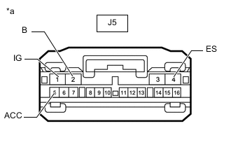
*a Front view of wire harness connector
(to Combination Meter Mirror ECU)
Disconnect the combination meter mirror ECU connector.
-
Measure the voltage according to the value(s) in the table below.
Standard Voltage Tester Connection Switch Condition Specified Condition J5-1 (IG) - Body ground Power switch on (IG) 11 to 14 V J5-2 (B) - Body ground Power switch off 11 to 14 V J5-5 (ACC) - Body ground Power switch on (ACC) 11 to 14 V -
Measure the resistance according to the value(s) in the table below.
Standard Resistance Tester Connection Condition Specified Condition J5-4 (ES) - Body ground Always Below 1 Ω Result Proceed to OK NG
NG 
REPAIR OR REPLACE HARNESS OR CONNECTOR
OK
-
-
INSPECT HEADUP DISPLAY SWITCH ASSEMBLY
-
Remove the headup display switch assembly.
-
Inspect the headup display switch assembly.
Result Proceed to OK NG
NG
REPLACE HEADUP DISPLAY SWITCH ASSEMBLY Click here
OK
-
-
CHECK HARNESS AND CONNECTOR (COMBINATION METER MIRROR ECU - HEADUP DISPLAY SWITCH ASSEMBLY)
-
Disconnect the J5 combination meter mirror ECU connector.
-
Disconnect the I70 headup display switch assembly connector.
-
Measure the resistance according to the value(s) in the table below.
Standard Resistance Tester Connection Condition Specified Condition J5-10 (SW2) - I70-10 (ILD) Always Below 1 Ω J5-9 (SW1) - I70-12 (ILU) Always Below 1 Ω J5-16 (E) - I70-6 (CH) Always Below 1 Ω J5-10 (SW2) or I70-10 (ILD) - Body ground Always 10 kΩ or higher J5-9 (SW1) or I70-12 (ILU) - Body ground Always 10 kΩ or higher J5-16 (E) or I70-6 (CH) - Body ground Always 10 kΩ or higher Result Proceed to OK NG
OK
REPLACE COMBINATION METER MIRROR ECU Click here
NG
REPAIR OR REPLACE HARNESS OR CONNECTOR
-
-
CONFIRM DTC OUTPUT (HEADUP DISPLAY)
-
Confirm DTC output.
Result Result Proceed to DTC is not output A DTC (01, 02) is output B DTC (03, 04) is output C
A
REPLACE COMBINATION METER MIRROR ECU Click here
C
CHECK FOR DTC (NAVIGATION SYSTEM, AUDIO AND VISUAL SYSTEM) Click here
B
-
-
CHECK HARNESS AND CONNECTOR (COMBINATION METER MIRROR ECU - COMBINATION METER ASSEMBLY)
-
Disconnect the J5 combination meter mirror ECU connector.
-
Disconnect the I10 combination meter assembly connector.
-
Measure the resistance according to the value(s) in the table below.
Standard Resistance Tester Connection Condition Specified Condition J5-6 (TX-) - I10-32 (TX-) Always Below 1 Ω J5-7 (CS) - I10-33 (CS) Always Below 1 Ω J5-6 (TX-) or I10-32 (TX-) - Body ground Always 10 kΩ or higher J5-7 (CS) or I10-33 (CS) - Body ground Always 10 kΩ or higher Result Proceed to OK NG
NG
REPAIR OR REPLACE HARNESS OR CONNECTOR
OK
-
-
CHECK COMBINATION METER ASSEMBLY
-
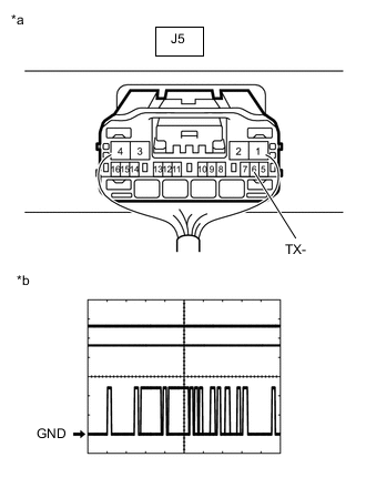
*a Component with harness connected
(Combination Meter Mirror ECU)
*b Waveform Remove the combination meter mirror ECU with the connector(s) still connected.
-
Connect an oscilloscope to terminal J5-6 (TX-) and body ground.
-
Check the signal waveform according to the condition(s) in the table below.
Measurement Condition Item Condition Tester connection J5-6 (TX-) - Body ground Tool setting 5 V/DIV., 200 μs./DIV. Vehicle condition Power switch on (IG) OK The waveform displayed is as shown in the illustration. Tech Tips
The period of the signal changes depending on the communication state.
Result Proceed to OK NG
NG
REPLACE COMBINATION METER ASSEMBLY Click here
OK
-
-
CHECK COMBINATION METER ASSEMBLY
-
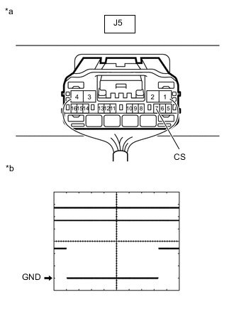
*a Component with harness connected
(Combination Meter Mirror ECU)
*b Waveform Remove the combination meter mirror ECU with the connector(s) still connected.
-
Connect an oscilloscope to terminal J5-7 (CS) and body ground.
-
Check the signal waveform according to the condition(s) in the table below.
Measurement Condition Item Condition Tester connection J5-7 (CS) - Body ground Tool setting 5 V/DIV., 2 ms./DIV. Vehicle condition Power switch on (IG) Tech Tips
The period of the signal changes depending on the communication state.
OK The waveform displayed is as shown in the illustration. Result Proceed to OK NG
OK
REPLACE COMBINATION METER MIRROR ECU Click here
NG
REPLACE COMBINATION METER ASSEMBLY Click here
-
-
CHECK FOR DTC (NAVIGATION SYSTEM, AUDIO AND VISUAL SYSTEM)
-
Check for DTCs.
w/ Navigation System: Click here
w/ Audio and Visual System (except 8 Speakers): Click here
w/ Audio and Visual System (for 8 Speakers): Click here
Body Electrical > Navigation System > Trouble CodesOK DTCs are not output. Result Result Proceed to OK A NG (w/ Navigation System) B NG (w/ Audio and Visual System [except 8 Speakers]) C NG (w/ Audio and Visual System [for 8 Speakers]) D
A
REPLACE COMBINATION METER MIRROR ECU Click here
B
GO TO NAVIGATION SYSTEM Click here
C
GO TO AUDIO AND VISUAL SYSTEM Click here
D
GO TO AUDIO AND VISUAL SYSTEM Click here
-